Nainstalovat Steam
přihlásit se
|
jazyk
简体中文 (Zjednodušená čínština)
繁體中文 (Tradiční čínština)
日本語 (Japonština)
한국어 (Korejština)
ไทย (Thajština)
български (Bulharština)
Dansk (Dánština)
Deutsch (Němčina)
English (Angličtina)
Español-España (Evropská španělština)
Español-Latinoamérica (Latin. španělština)
Ελληνικά (Řečtina)
Français (Francouzština)
Italiano (Italština)
Bahasa Indonesia (Indonéština)
Magyar (Maďarština)
Nederlands (Nizozemština)
Norsk (Norština)
Polski (Polština)
Português (Evropská portugalština)
Português-Brasil (Brazilská portugalština)
Română (Rumunština)
Русский (Ruština)
Suomi (Finština)
Svenska (Švédština)
Türkçe (Turečtina)
Tiếng Việt (Vietnamština)
Українська (Ukrajinština)
Nahlásit problém s překladem


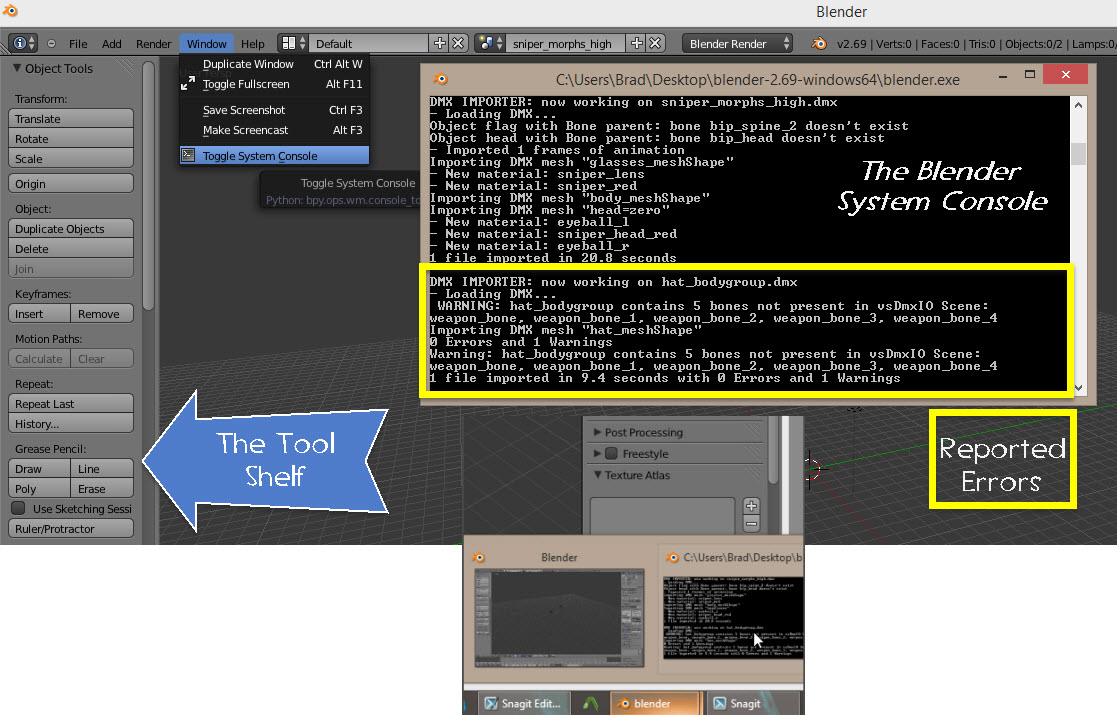


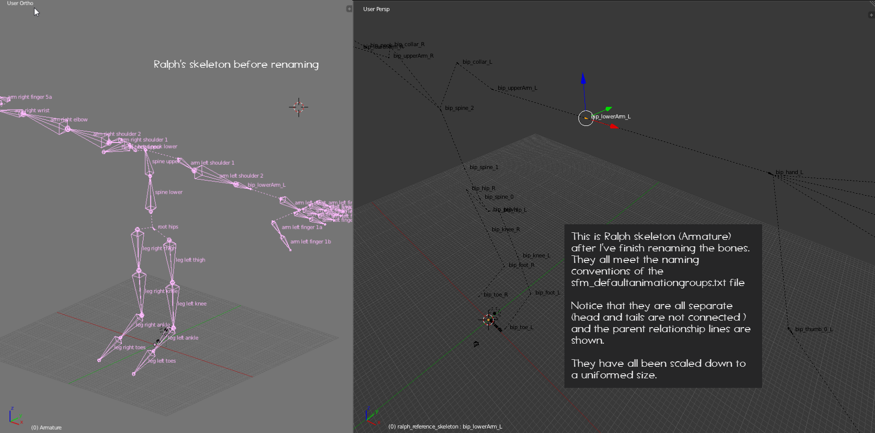


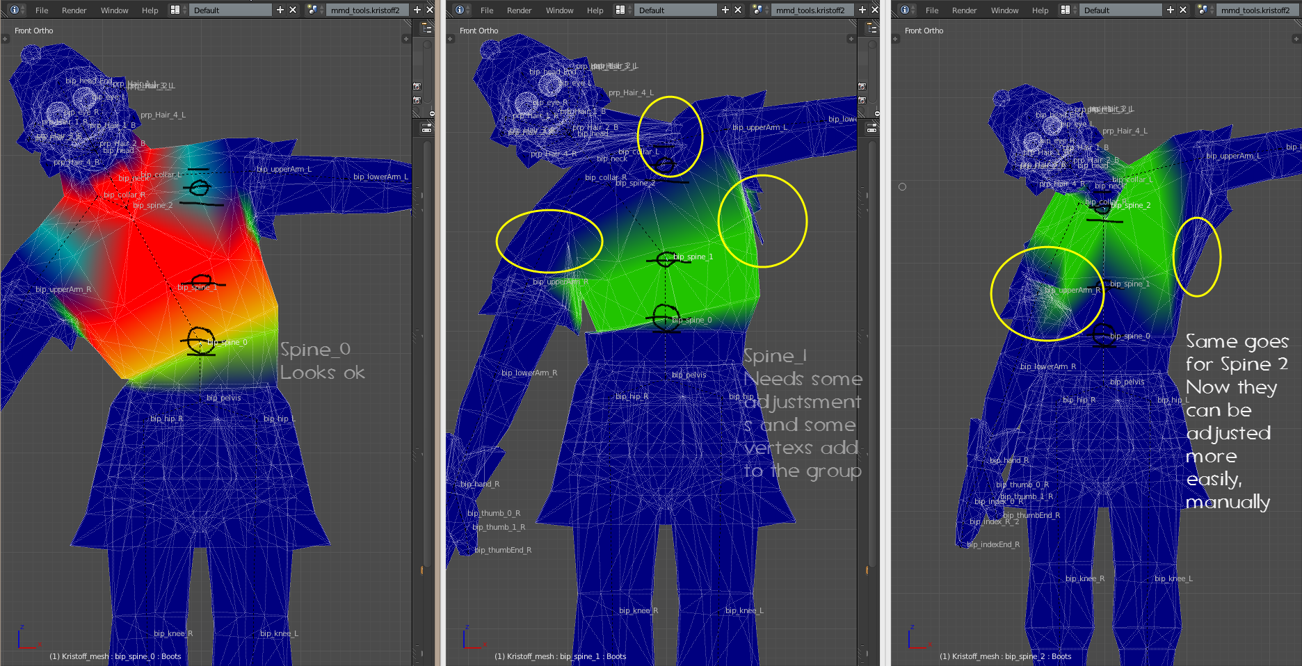


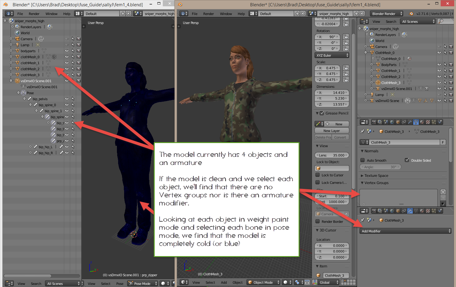


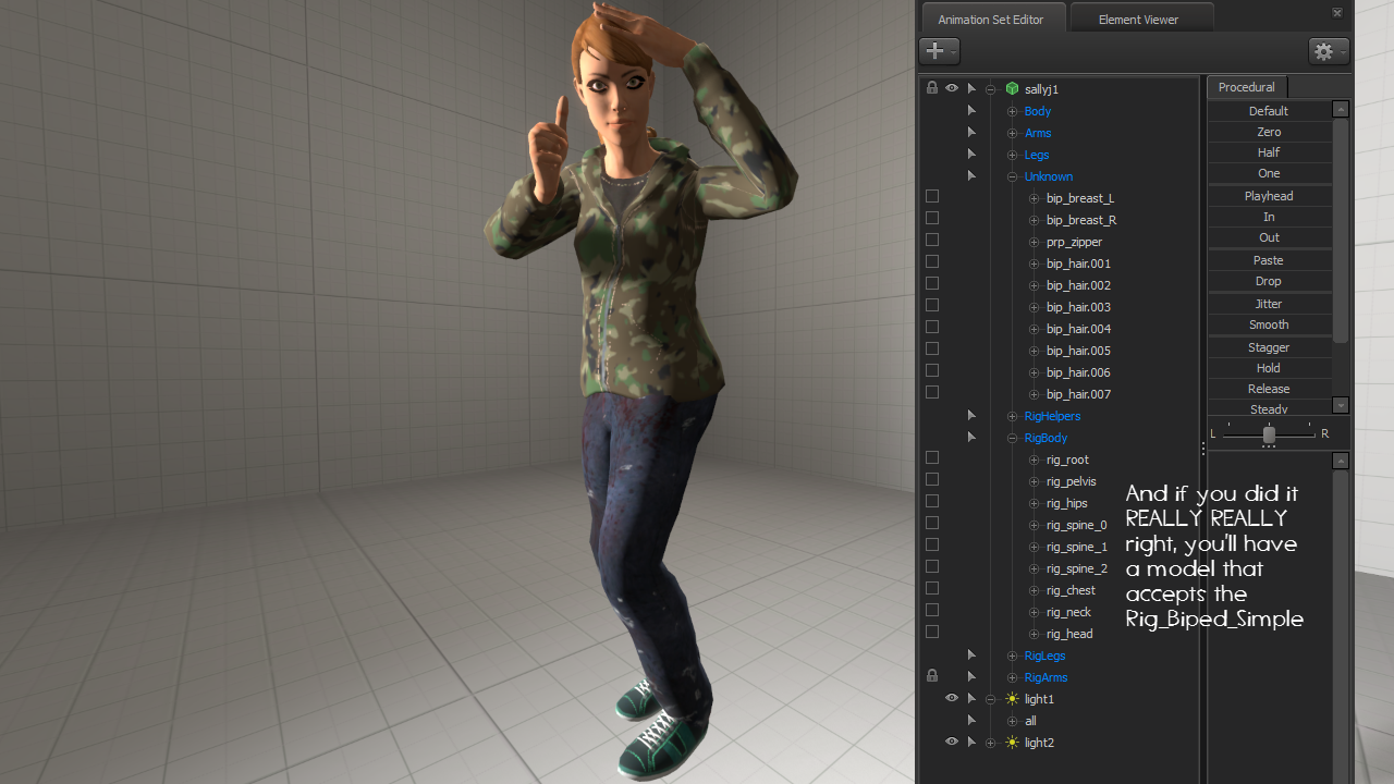

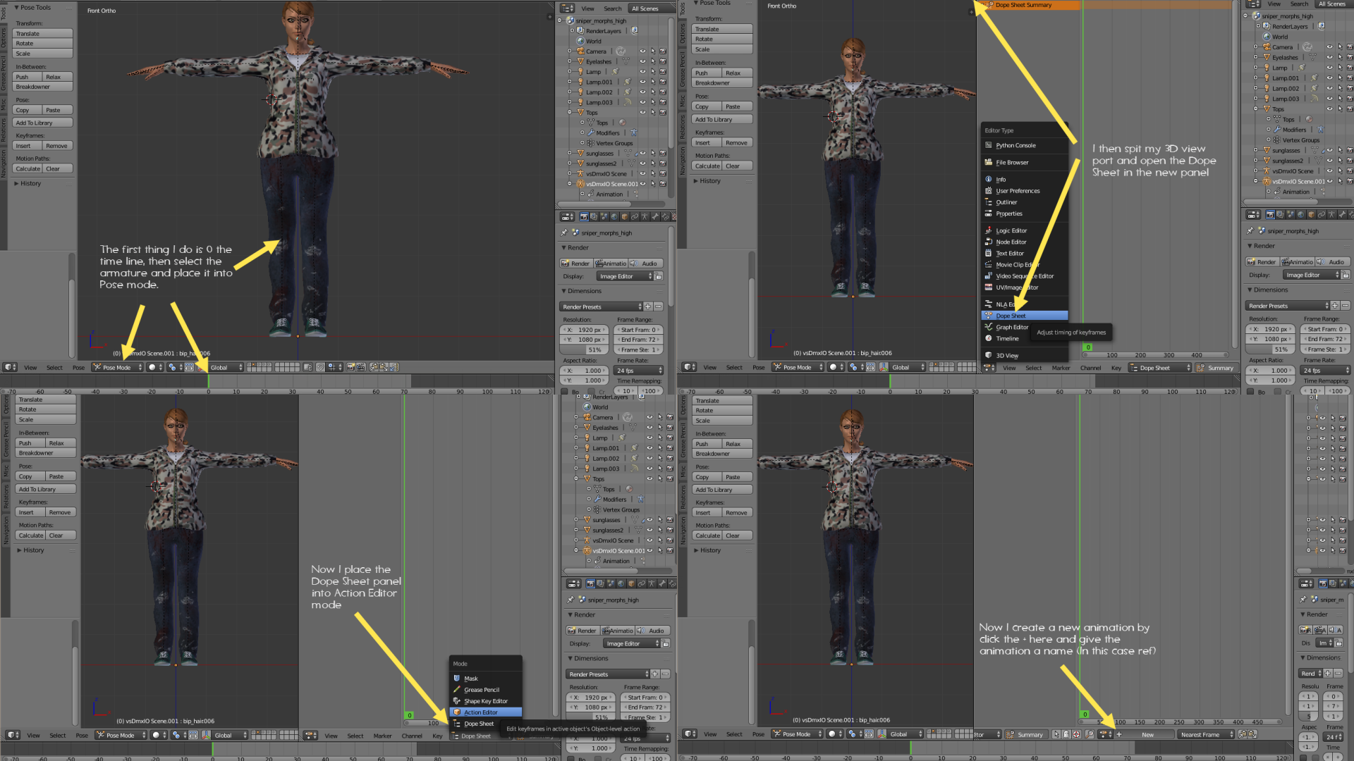
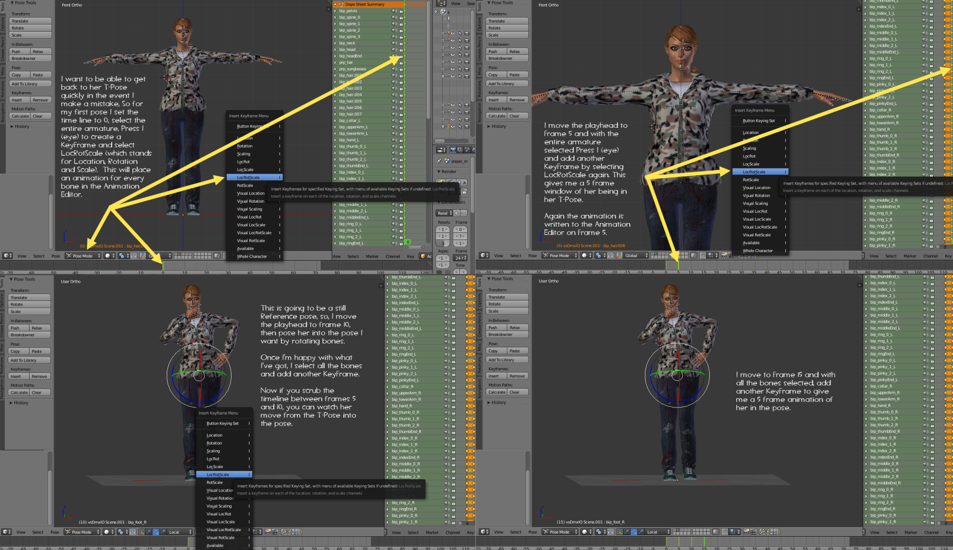


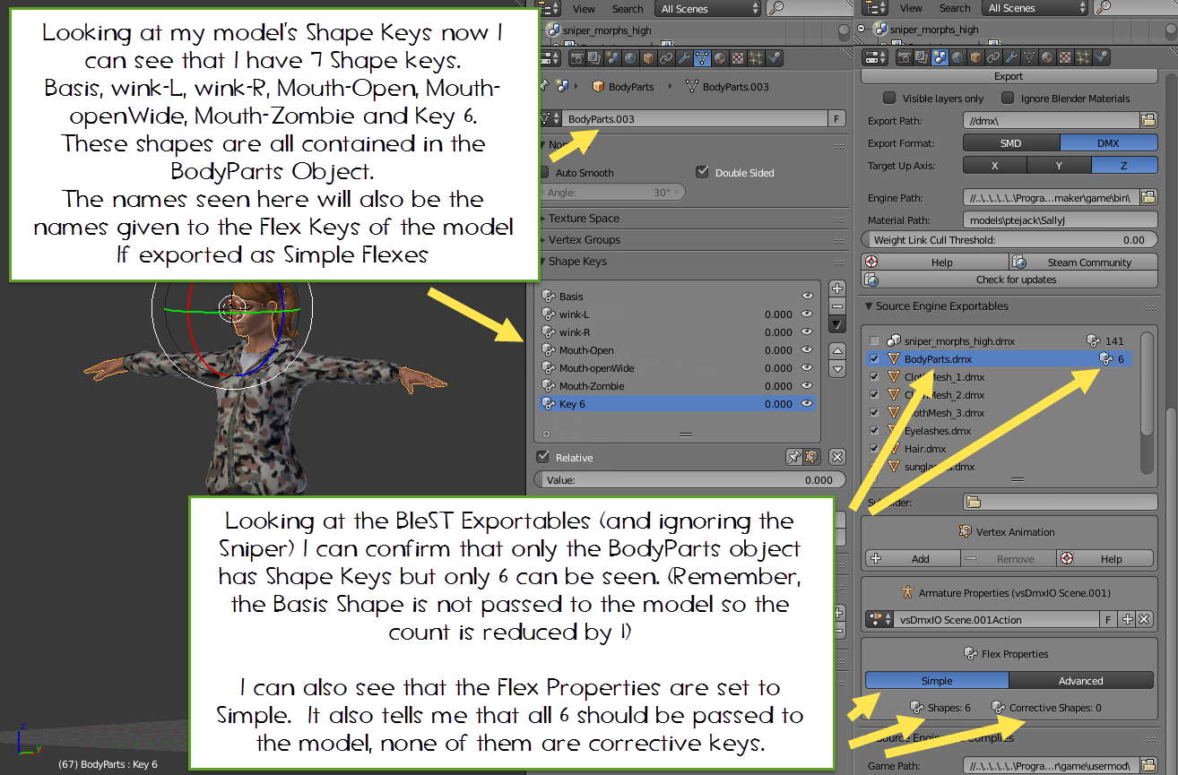
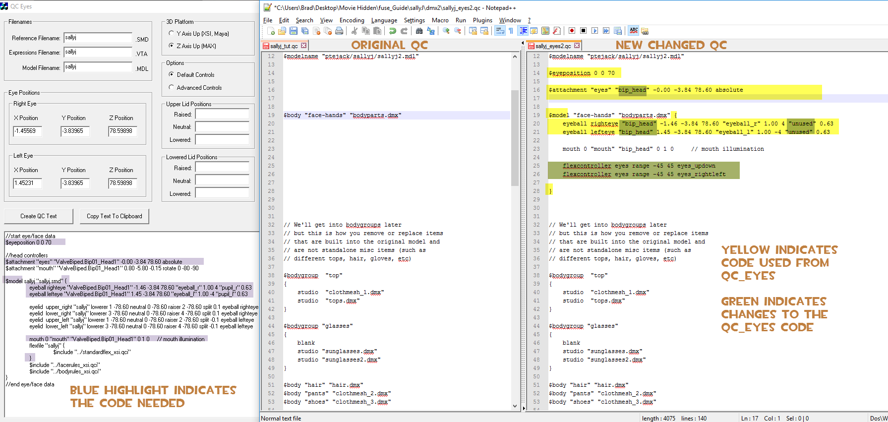


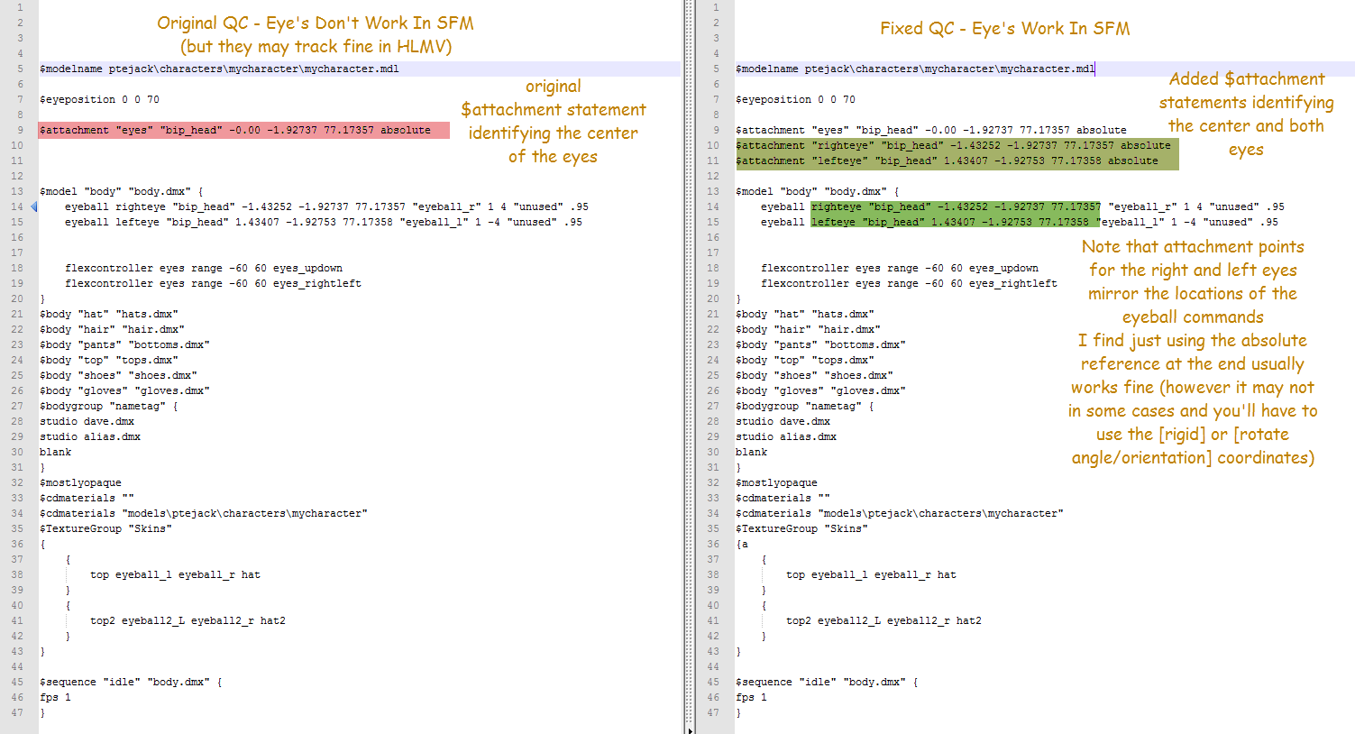


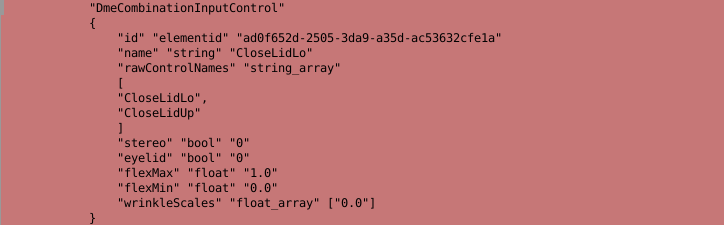
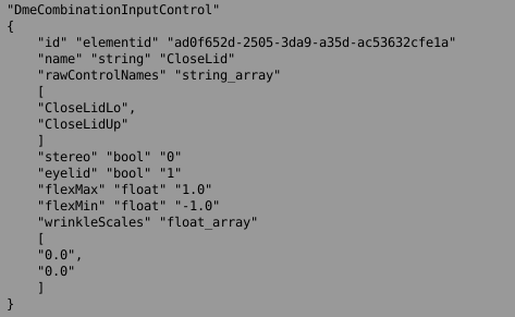
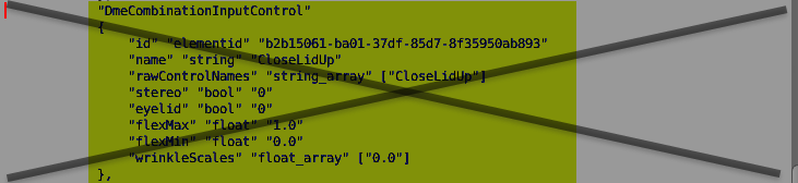


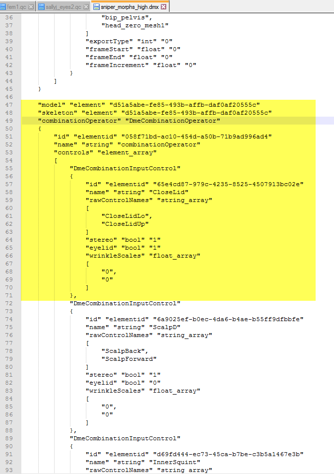

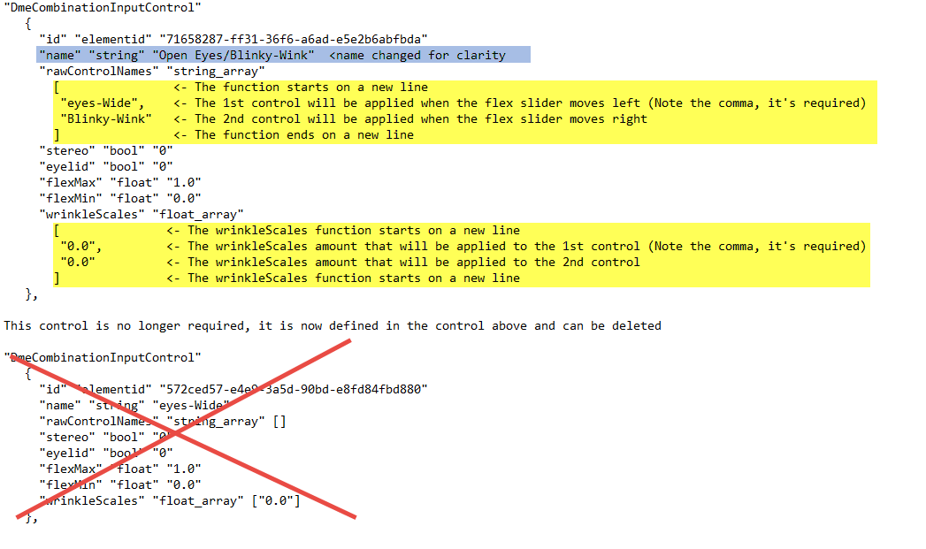


good guide though.
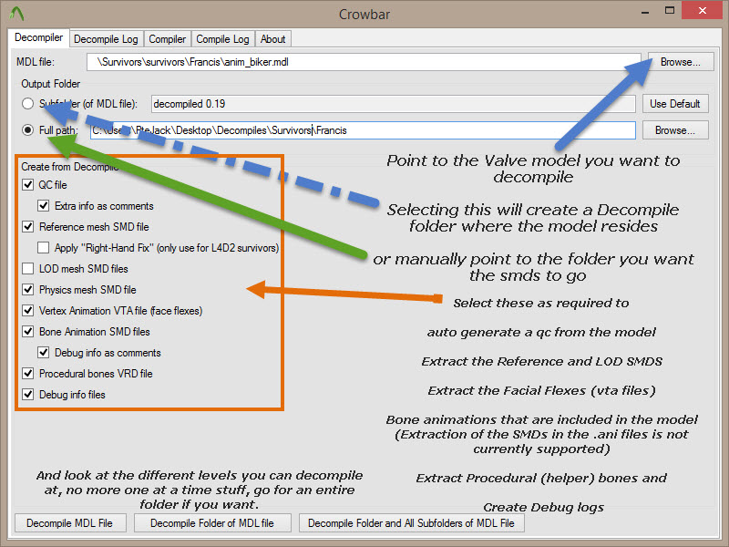
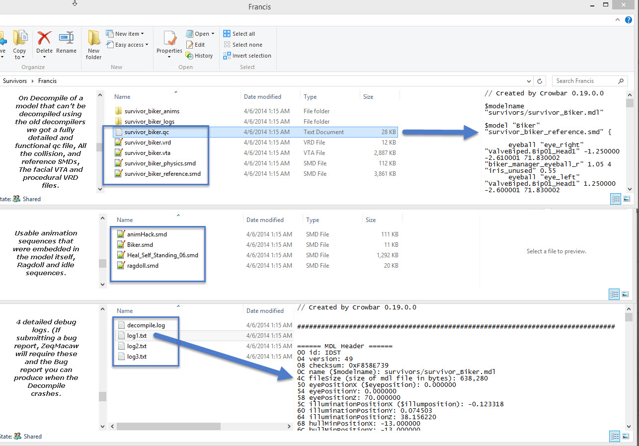
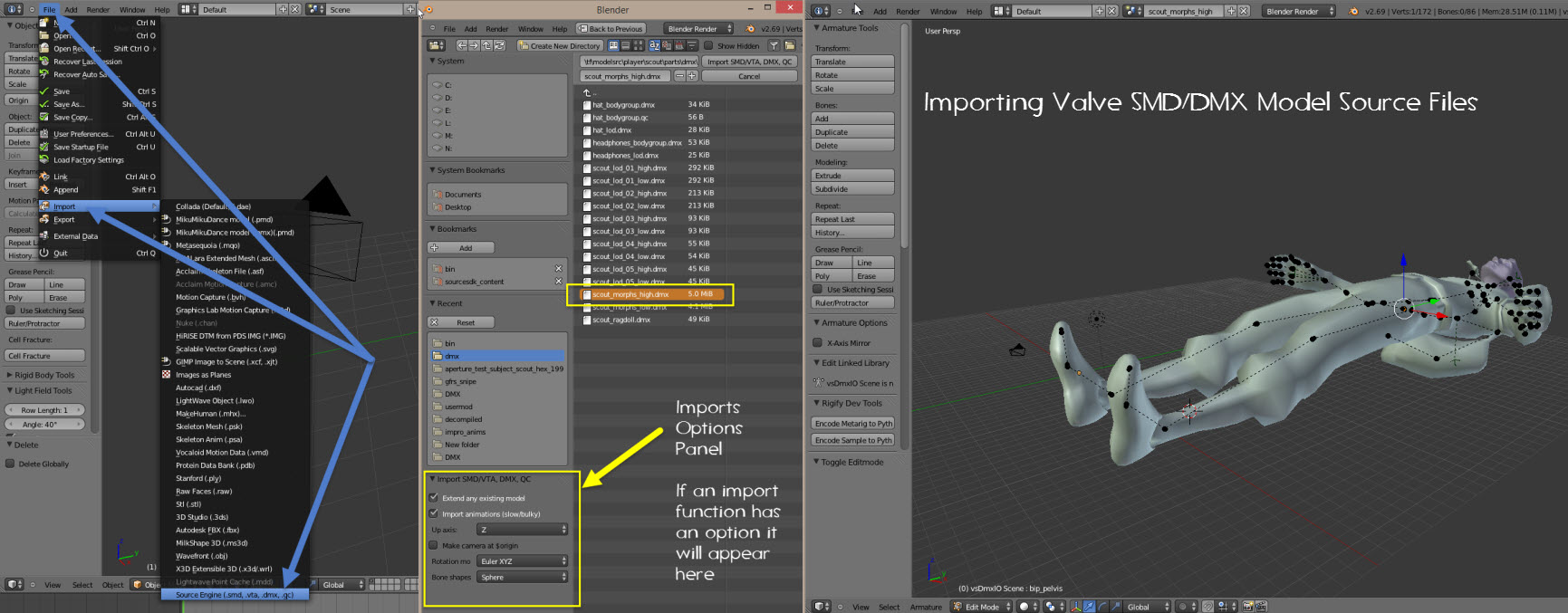
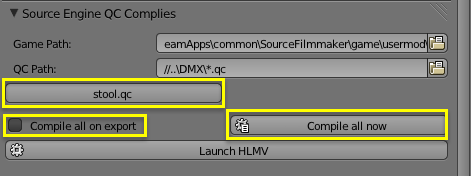
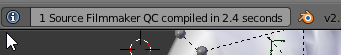
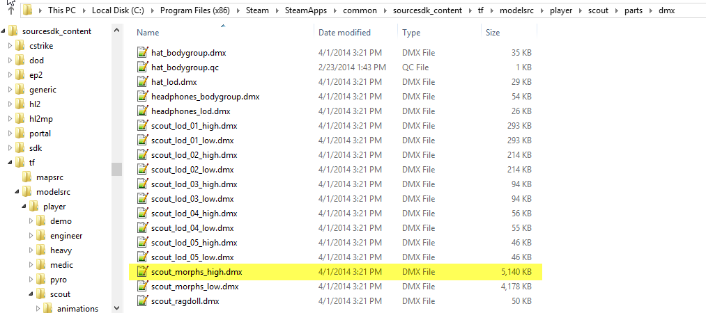
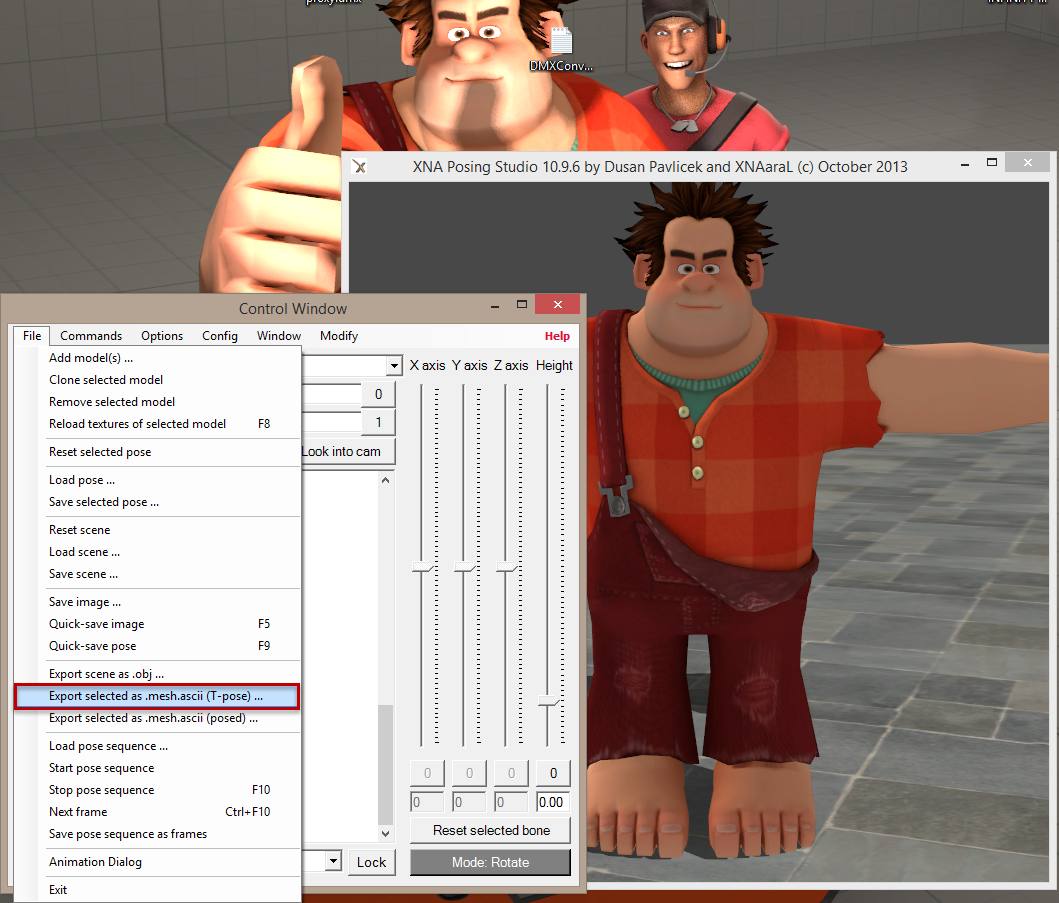
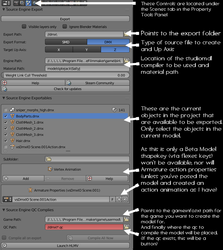
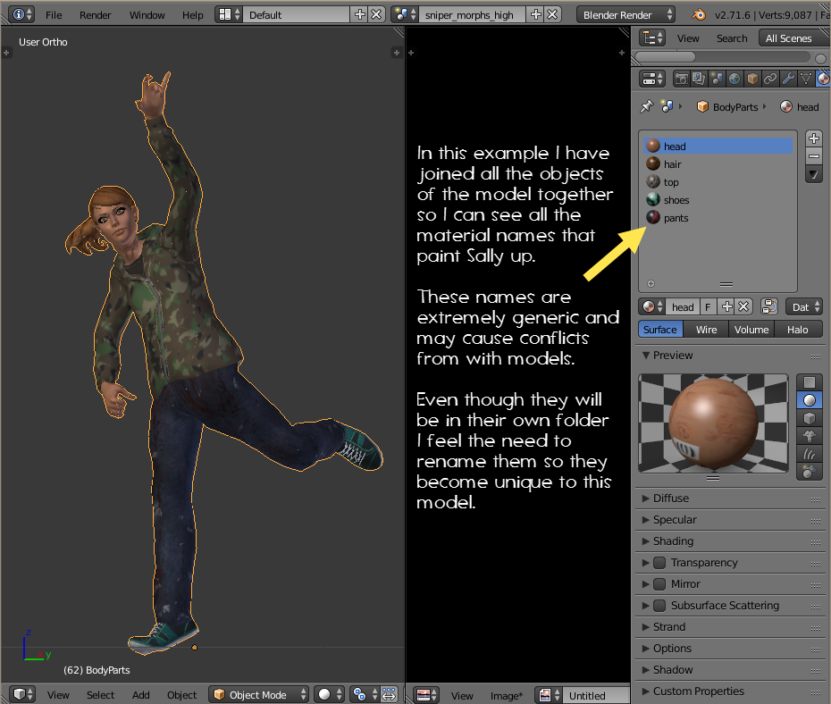
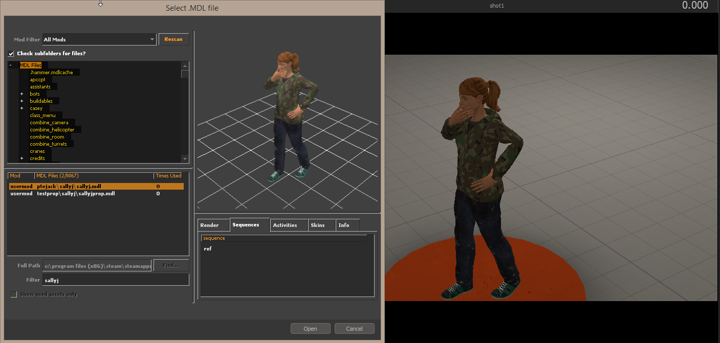
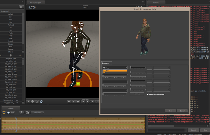
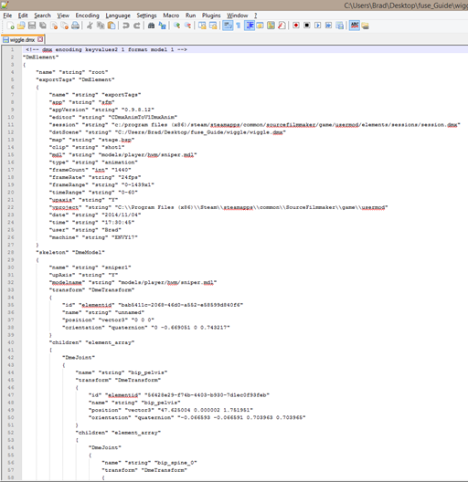
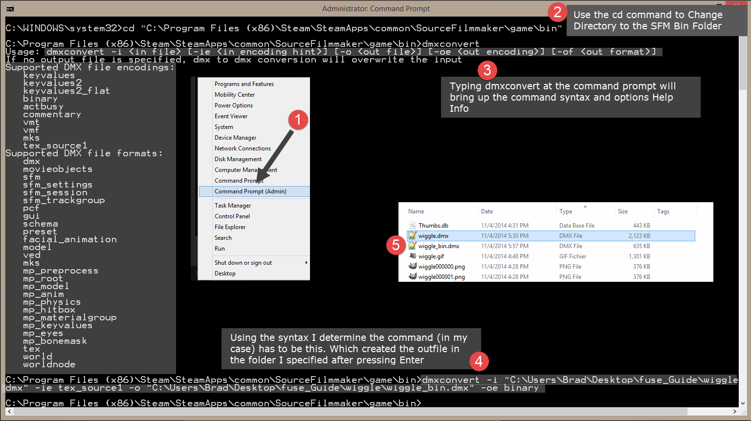
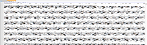
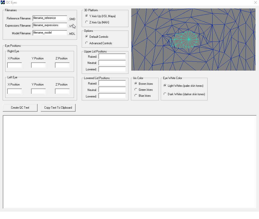
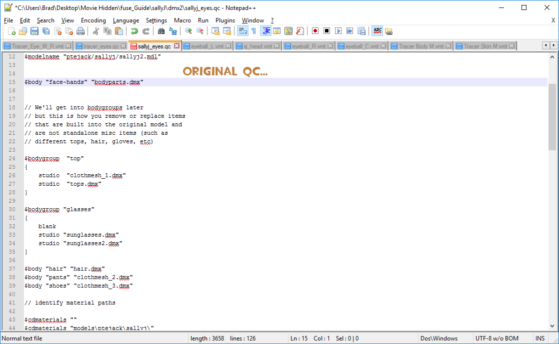
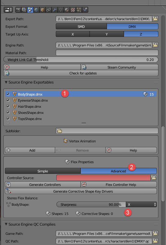
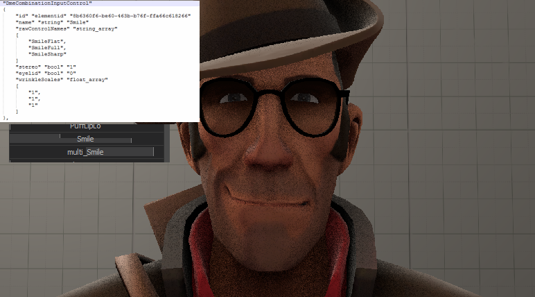
or just how to change .smd/.dmx to .mdl
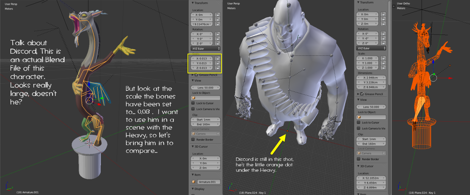
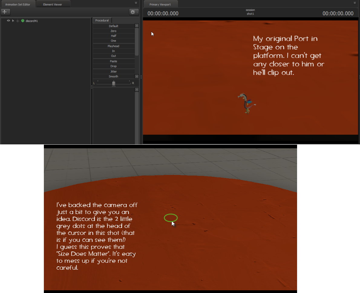
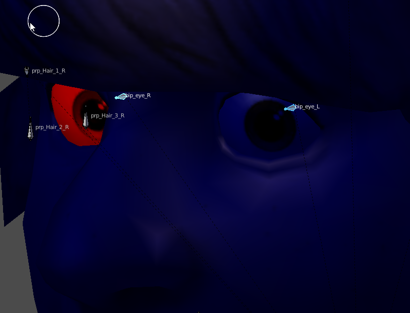
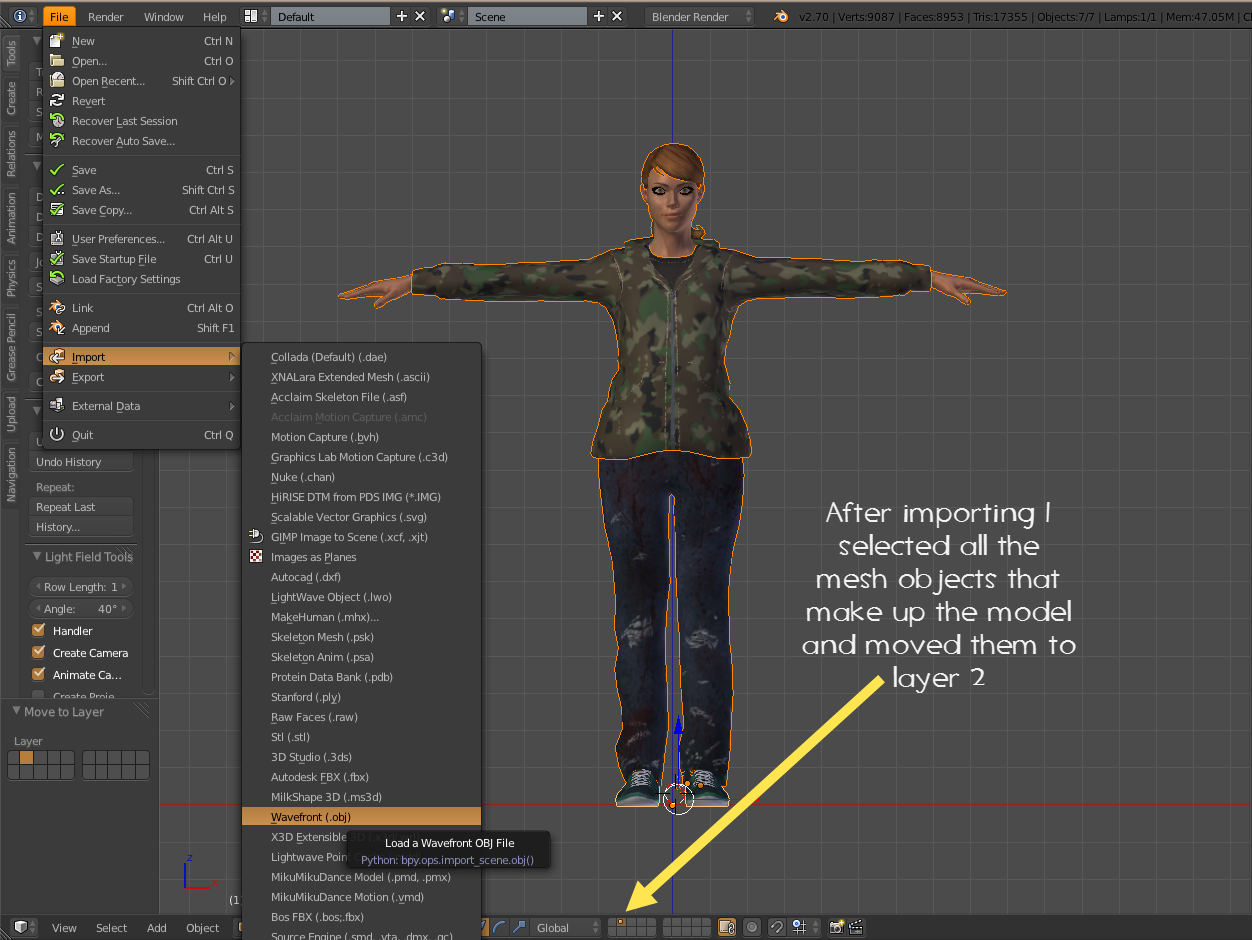
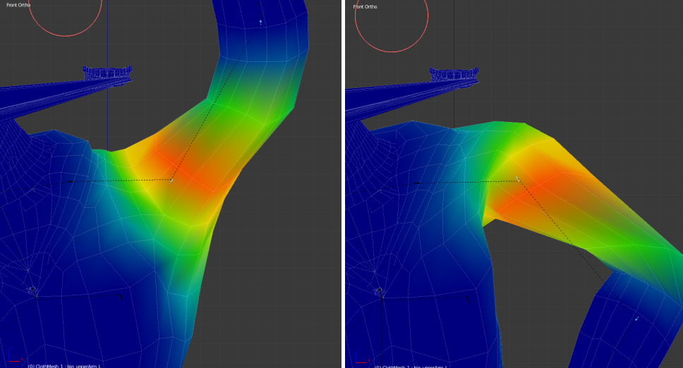
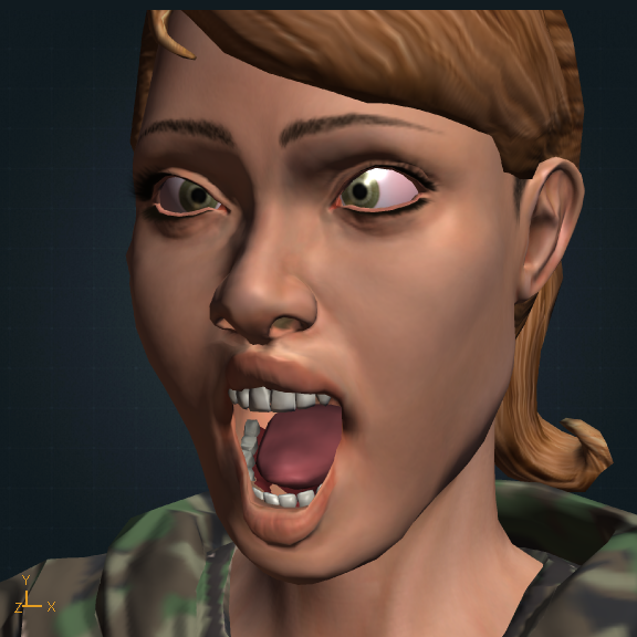
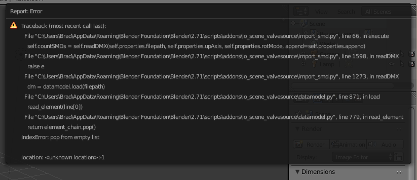
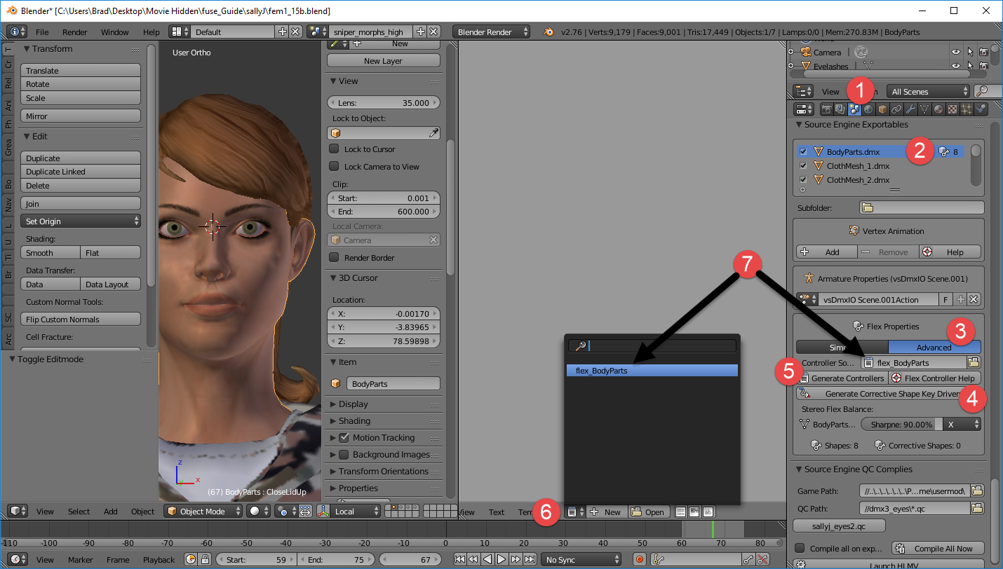
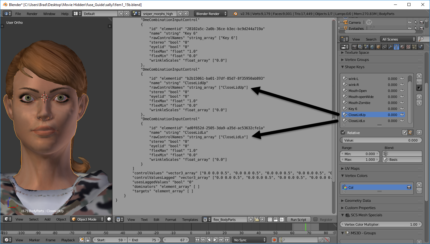
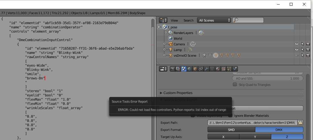
I mean I can try but I didn't know that import a non-sfm model was that difficult 💀