NoLimits 2 Roller Coaster Simulation

NoLimits 2 Roller Coaster Simulation

41 Bewertungen
Building a Control Panel
Von KingdaToro
A guide for building a physical ride operator's control panel for controlling coasters in NoLimits 2, using the actual industrial controls most commonly used on real coaster control panels.
2
2
   
Preis verleihen
Favorisieren
Favorisiert
Entfernen
Introduction
This is a full tutorial for building an authentic physical control panel for NoLimits 2. It will be able to do everything the station controls on the in-game panel can do. It can control the restraints, control the gates, control the movable floors for floorless coasters and the movable seats for flying coasters, dispatch the trains, and control the emergency stop.

Building this panel requires some basic tools: A philips screwdriver, a wire stripper and cutter, a large adjustable wrench (or equivalent) a drill with bits suitable for drilling steel, and some way to cut a roughly 1 square centimeter hole in steel. A dremel will work for this.

Before building this panel, just be aware that it will be expensive. The controls and enclosure are all authentic industrial-grade products, so they will cost a lot more than you expect. They should, by all means, be bought used. I'll go into more detail on this later.

It consists of six major elements: The controls, the enclosure, the legend plates, the lights, the wires, and the "brain".

Before building such a panel, you need to make one major decision: the number of controls. The bare minimum for full functionality is six: Dispatch, Gates, Restraints, Seats/Floor, Trouble/Reset, and Emergency Stop. A more authentic panel has eight controls, it adds a Control Power switch and a second Dispatch button. On this panel, both Dispatch buttons must be pressed together, which is typical on real coasters. This is what I built, and is what this guide will generally cover.


Demo video of my panel:
The Controls
The controls used in this panel are Allen-Bradley's 800T line. They're the controls most commonly found in real coasters. They typically cost over $100 each new, so you'll want to buy them used on eBay whenever possible. You should ideally be able to get them there for $30 each or less.

With these buttons, there are different options for lighting. What you want is buttons with direct connections to the bulb socket that are designed to run on low voltage, not with power transformers that are intended to run on 120V line voltage and step it down to a low voltage for the bulb. This is already part of the model numbers, the "24" indicates a 24V incandescent bulb. You'll be replacing these with 5V LED bulbs, anyway.

The Dispatch Button(s)
For your dispatch button(s), you'll want a green guarded, illuminated pushbutton. The model number to search for is 800T-QA24G. Get one if you're doing a six-control panel, or two if you're doing an eight-control panel.

The Gates, Restraints, and Seats/Floor Buttons
For these three controls, you'll want three amber guarded, illuminated pushbuttons. The model number to search for is 800T-QA24A.

The Reset Button
This button can be either blue or red. Reset buttons are typically blue, but in this case it makes sense to combine it with your trouble light. That's what I did. In this case, it should be red. And besides, NL2's reset button is red. Like the previous ones, this will be a guarded, illuminated pushbutton.
For a red button: 800T-QA24R
For a blue button: 800T-QA24B

The Emergency Stop Button
This one's a little different from the rest. It's not guarded, instead it has a large "mushroom" head to make it very easy to press quickly. It also has a push-pull function, it stays pushed in and has to be pulled back out to deactivate it. Needless to say, it must be red. You've got a couple of options here, you can go with a smaller "standard" head made of plastic and metal, or with an even larger "jumbo" all-plastic head. You also have the option of being able to twist the button clockwise to release it, or not. I recommend the standard head. The buttons will be quite close together, so the jumbo head may come too close to the others for comfortable operation.

Push-pull, standard head (recommended): 800T-FXQ24RA
Push-pull, jumbo head: 800T-FXJQ24RA
Push-pull/twist, standard head: 800T-FXTQ24RA
Push-pull/twist, jumbo head: 800T-FXJTQ24RA

Standard head[parts.santaclarasystems.com]
Jumbo head[parts.santaclarasystems.com]

The Control Power Switch
This will be a two-position selector switch. You'll only get one at all if you're doing an eight-control panel, ignore this section completely if you're only doing six. The most authentic choice here is a keyswitch, but you can just as easily go for a standard switch. For a keyswitch that only allows the key to be removed in the left (off) position, look for the 800T-H31A. If you want to be able to remove the key in both positions, go for the 800T-H33A instead. These take a standard key called the D018, you can find them anywhere. If you don't want to bother with a key, go with a standard switch instead, the 800T-H2A.
The Enclosure
The enclosure you'll want for this project is a "consolet" for 30mm pushbuttons. It will have a specific number of pushbutton holes, obviously you'll want to match this to the number of controls you're using. Like the controls themselves, this will be expensive, so try to get a used one from eBay. You've got several manufacturers to choose from, look for any of these and try to get the cheapest one.

For an 8-control panel:
Wiegmann WPBA8
Hoffman E8PBA
Hammond 1490G8
Saginaw SCE-8PBA


For a 6-control panel:
Wiegmann WPBA6
Hoffman E6PBA
Hammond 1490G6
Saginaw SCE-6PBA
The Legend Plates
Legend plates are the labels for your buttons. Typical industrial control panels use standard terms on theirs, with terms like "START", "STOP", "JOG" etc. These are commonly available, but roller coasters use fairly non-standard terminology, so you're going to need custom ones. Fortunately, this is easier than it sounds.

Dispatch legend plate - single line[www.legend-plates.com]
Text should say "DISPATCH". The color scheme can be anything that doesn't have a red or yellow background. I recommend a green background with white text. Remember to get two if you're doing an 8-control panel!

Gates, Restraints, Seats/Floor legend plates - two line[www.legend-plates.com]
These can use any color scheme that doesn't have a red or yellow background, I suggest a black background and white text. The text should be as follows:
Gates, text line 1: GATES
Gates, text line 2: OPEN/CLOSE
Restraints, text line 1: RESTRAINTS
Restraints, text line 2: LOCK/UNLOCK
Seats/floor, text line 1: SEATS/FLOOR
Seats/floor, text line 2: RAISE/LOWER

Emergency Stop legend plate - two line[www.legend-plates.com]
This should use the industry standard color scheme for emergency stops, a yellow background with red text. Line 1 should say "EMERGENCY" and line 2 should say "STOP".

Control Power legend plate - selector switch[www.legend-plates.com]
Title text should be "CONTROL POWER", left text should be "OFF", and right text should be "ON". The color scheme can be anything without a yellow or red background, I suggest black text on a white background. Remember, this is only for an 8-control panel!

And last but not least, the Reset button. This depends on how you want to use it. I use it as a combined reset button and trouble light, so the button itself is red, and I went with a 2-line legend plate with "TROUBLE" as the first line and "RESET" as the second. Color scheme is white text on a red background.
The Lights
The Allen-Bradley 800T controls used for this panel use a standard BA9S socket, and the Arduino that's the "brain" of the panel puts out 5 volt power, so you're going to want 5V LED bulbs that fit a BA9S socket. You can find them here:

https://www.superbrightleds.com/moreinfo/bayonet-base-bulbs/ba9s-led-landscape-light-bulb-4-led-ba9s-retrofit/2538/

You have two options here. The simpler option is to go with all white bulbs (BA9S-WW4-32-6VAC), but this isn't ideal. What will look much better is matching the bulb colors to your button colors. For this you'll need...

One or two greens (BA9S-G4-32-6VAC) for your dispatch button(s). One for six controls, two for eight.

Three ambers (BA9S-A4-32-6VAC) for your gates, restraints, and seats/floor buttons.

One or two reds (BA9S-R4-32-6VAC). One for your E-stop, one for your Reset button if you use a red one. If you use a blue Reset button, get a blue bulb (BA9S-B4-32-6VAC).

Your Control Power switch isn't illuminated, so no bulb needed there.
The "Brain" and Wires
The "brain" of the panel will be an Arduino Leonardo[smile.amazon.com]. It will connect to your PC via USB, and all the panel's controls will connect to its pins.

You're going to need some way to get the USB cable into the panel. For this, you can use a pass-through port[smile.amazon.com]. It doesn't come with screws, so you'll need these[smile.amazon.com]. Installing this part will be tricky, as you'll need to drill the screw holes and cut the port hole in the panel enclosure.

You'll need wires to connect the Arduino to the controls. For this, use breadboard jumpers[smile.amazon.com] since they can plug directly into the Arduino.

You'll also want some single-strand hook-up wire. This is for your ground connections, as you'll need to connect half of all your terminals together and to the ground pins of the Arduino. This makes it a lot easier.
Assembling the panel
The first thing you need to do when assembling the panel is to decide on the layout of the controls. The Dispatch buttons should go in the bottom corners, Gates and Restraints should be between them, Control Power should be at the top left, and the E-stop should be at the top right. But it's up to you, of course. This is the layout I used:

Top row: Control Power, Trouble/Reset, Seats/Floor, E-Stop
Bottom row: Dispatch, Gates, Restraints, Dispatch

Once you decide on your layout, apply your legend plates. Remove the backing from the adhesive, and line it up carefully over the appropriate button hole in the enclosure. Make sure the notch at the top of the plate's hole is lined up with the upper notch in the enclosure hole. Press it down when satisfied with the alignment, and repeat for all the others.

Next, you need to disassemble your controls. This is a bit different for the different types of controls.
  • Remove the guard, by unscrewing counterclockwise. This is only present on the illuminated, guarded pushbuttons. It's the hollow metal cylinder with holes in the sides.
  • Remove the lens, by unscrewing counterclockwise. This is the colored plastic part present on all the illuminated controls. On the E-stop, it's the mushroom head.
  • Remove the bulb, if present, by pushing inward and turning slightly counterclockwise. You won't need these bulbs.
  • Remove the lock washer by unscrewing counterclockwise. This is the part with an octagonal rim, that you can use a wrench on. It's very small on the guarded buttons, but significantly larger on the E-stop and control power switch.
  • Remove the alignment washer. This is the circular part with a tab sticking down.
  • Leave the rubber rings in place. If possible, make sure each control has at least two.

If your controls are used, clean the guards, lenses, lock washers, and alignment washers at this time. In particular, the holes in the guards can get quite dirty.

Now, you need to familiarize yourself with the contact blocks of the controls. This is the part all the way at the bottom, and is where you'l make your connections. You'll see one side with four screw terminals, and one with two. The side with two terminals is for powering the light, it has a L1(+) terminal for power, and a (-)L2 terminal for ground. Remember which is which.

The side with four terminals is for the control, it looks like this:
The N.C. terminals are connected when the button is released, the N.O. terminals are connected when it's pressed. You will almost always use only the N.O. terminals, the only exception is the E-stop. For that, you'll use the N.C. terminals, so that any breaks in the E-stop circuit will trigger the E-stop rather than making it inoperable.

Finally, it's time to install the controls.
  • Remove the top of the enclosure by unscrewing the screws. Set the base aside for now.
  • Insert a control into its appropriate hole, from below. Orient it so that the light terminals face the center, and the control terminals face the top or bottom. This will make wiring much easier.
  • Install the alignment washer, making sure its tab goes into the notches in the legend plate and enclosure hole
  • Install the lock washer, and tighten with a wrench
  • Repeat the above steps for all the rest of the controls
  • Install the bulbs. These will be your new LED bulbs, not the incandescents that came with the buttons. Make sure to put the appropriate color bulbs in the appropriate buttons. Install them by pushing down and twisting slightly to the right.
  • Install the lenses, making sure to match the colors of the bulbs
  • Install the guards. They only need to be finger-tight, no need for a wrench.

At this point, the inside of the panel should look something like this, but without the wires:


Finally, install the USB pass-through port into the base of the enclosure. You'll need to figure out where to put it, make the appropriate holes for the screws and port, and mount it. This is what mine looks like...


Wiring the panel
The ground wiring
Everything on the panel works through the Arduino detecting whether one of its pins is connected to ground, or by sending power out through one of its pins, through a LED bulb, and then to ground. This means that one terminal of each control, and one terminal of each light, must all be connected together and to the GND pins on the Arduino.

To do this, you'll want to make a long daisy-chain with your hook-up wire. To wire a terminal, loosen the screw, insert one wire on one side of the screw or two wires on both sides, and tighten the screw. Connect one of the N.O. terminals on one of the controls in a corner to one of the N.O. terminals on the next one, and keep going, connecting one N.O. terminal of each control all together. When you get to the end of the row, connect a wire going around the end, to the middle, and to the first (-)L2 light terminal. Keep going, connecting all the (-)L2 light terminals together. Then go around the end again, to the other row of control terminals, and connect one N.O. terminal on each of these controls all together. Remember to use a N.C. terminal on the E-stop rather than a N.O.

When you're done, the wiring should look something like this:


Wiring the Arduino
This is where you'll use your breadboard jumpers. For each connection, you'll want to use a jumper with at least one male end, which plugs into the Arduino. You'll cut the plug off the other end, strip the wire, and clamp it in a terminal as usual.

First, make your ground connections. Use two jumpers, and connect one to each end of your ground wiring "chain", that is, under the only ground terminals that have only one wire in them. Plug the jumpers into two GND pins on the Arduino. This is for redundancy, everything will still work if a ground wire breaks.

For all the light connections, you'll use the terminal without a ground connection, the L1(+) terminal. Make the following connections:

E-Stop light to pin 0
Trouble light to pin 8
Seats/Floor light to pin 9
Gates light to pin 10
Restraints light to pin 11
Dispatch light to pin 12
Second Dispatch light to pin A1, if you're using two.

For the control connections, you'll connect the N.O. terminal without a wire on it to the appropriate pin. Remember to instead use the N.C. terminals on the E-stop. Make the following connections:

Control Power switch to Pin 1, if you're using one.
Reset button to pin 2
Seats/Floor button to pin 3
E-Stop to pin 4
Gates button to pin 5
Restraints button to pin 6
Dispatch button to pin 7
Second Dispatch button to pin A0, if you're using one.

When done, it should look similar to this:


Finally, connect the pass-through port's plug to the Arduino, and close the panel. Don't tighten the screws yet, make sure everything works right first.
Programming the Arduino
I'm not about to teach you Arduino programming here, I'm just going to give you my code to use.

The first step is to download and install the Arduino IDE[www.arduino.cc].

In the IDE, go to Tools>Board and choose Arduino Leonardo. Copy and paste the code[pastebin.com] into the IDE, and save the sketch, naming it something like nl2_panel. Make sure to set the panelHasEightButtons variable to false if you're using a six-button panel without a power switch and second dispatch button.

Connect the Arduino to the PC with a USB cable, and once it's recognized, press Upload, the right arrow button right under the Edit menu. If everything goes well, the panel should be ready to use.
Using The Panel
To use the panel, get close enough to a coaster that you can see its in-game control panel (F4), and set the station to manual dispatch. Turn on the panel's control power. The panel will go into a self-test mode. All the button lights will turn on, you need to press each button to test it and turn off its light. This will have no effect on the simulator. Once you've pressed all of them and pulled the E-stop back out, the panel will go into its normal operating mode.

All the lights on the panel share a common pattern: Off means unavailable, flashing means available and in the proper position for dispatch, and on means available and not in proper position for dispatch. It also indicates active movement.

The panel's default state reflects a coaster's default state: in the station, with gates and restraints closed, ready to dispatch, with the E-stop available. You'll see the gates, restraints, dispatch, and E-stop buttons all flashing, to indicate this. Pressing either gates or restraints will open them, set its light to on, and turn off the dispatch lights. Pressing both dispatch buttons will turn them on and the other lights off, until the next train parks in the station.

For floorless or flying coasters, pressing Seats/Floor will put the panel in the appropriate mode. In this mode, you need to press Seats/Floor between moving the gates and restraints, and dispatching the train. Once the gates and restraints are closed, the Seats/Floor light will turn on. Pressing it will move the seats/floor to dispatch position, and the Seats/Floor and Dispatch lights will flash. When the next train comes in, you'd press Seats/Floor to move it to loading position and enable the Gates and Restraints buttons.

Reset simply resets all the panel's variables to their default state. It's also the only way to get out of flyer/floorless mode. It's meant to be used alongside the coaster's in-game reset button, but can't actually trigger it.

The E-stop toggles the in-game E-stop, and disables dispatch. The gates, restraints, and seats/floor are movable in game with the E-stop on, so the panel allows this as well.

The Trouble light will illuminate whenever pressing a button for a function that's unavailable, or if you try to reset the panel with the E-stop engaged.

All of this is faked with timers, the panel can't actually communicate back and forth with NL2. It just sends keystrokes. It may be possible to use NL2's telemetry server for two-way communication, but I have no idea how to make the Arduino talk to it.
9 Kommentare
billycherry789 27. März um 4:16 
How do I change the restraints/gates button to be switch’s what’s the coding for it? Thank you
Fearless Grandad 7. Jan. 2024 um 10:45 
Great tutorial, Finished building the panel, only problem on the one we built is the E stop.
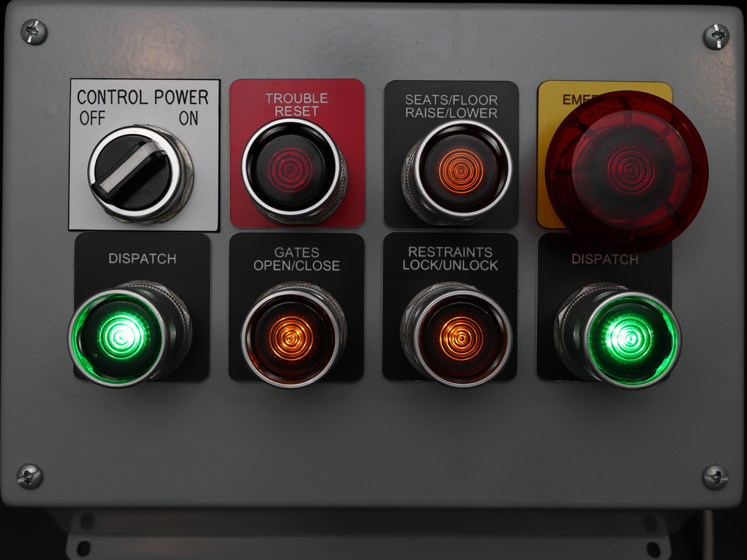
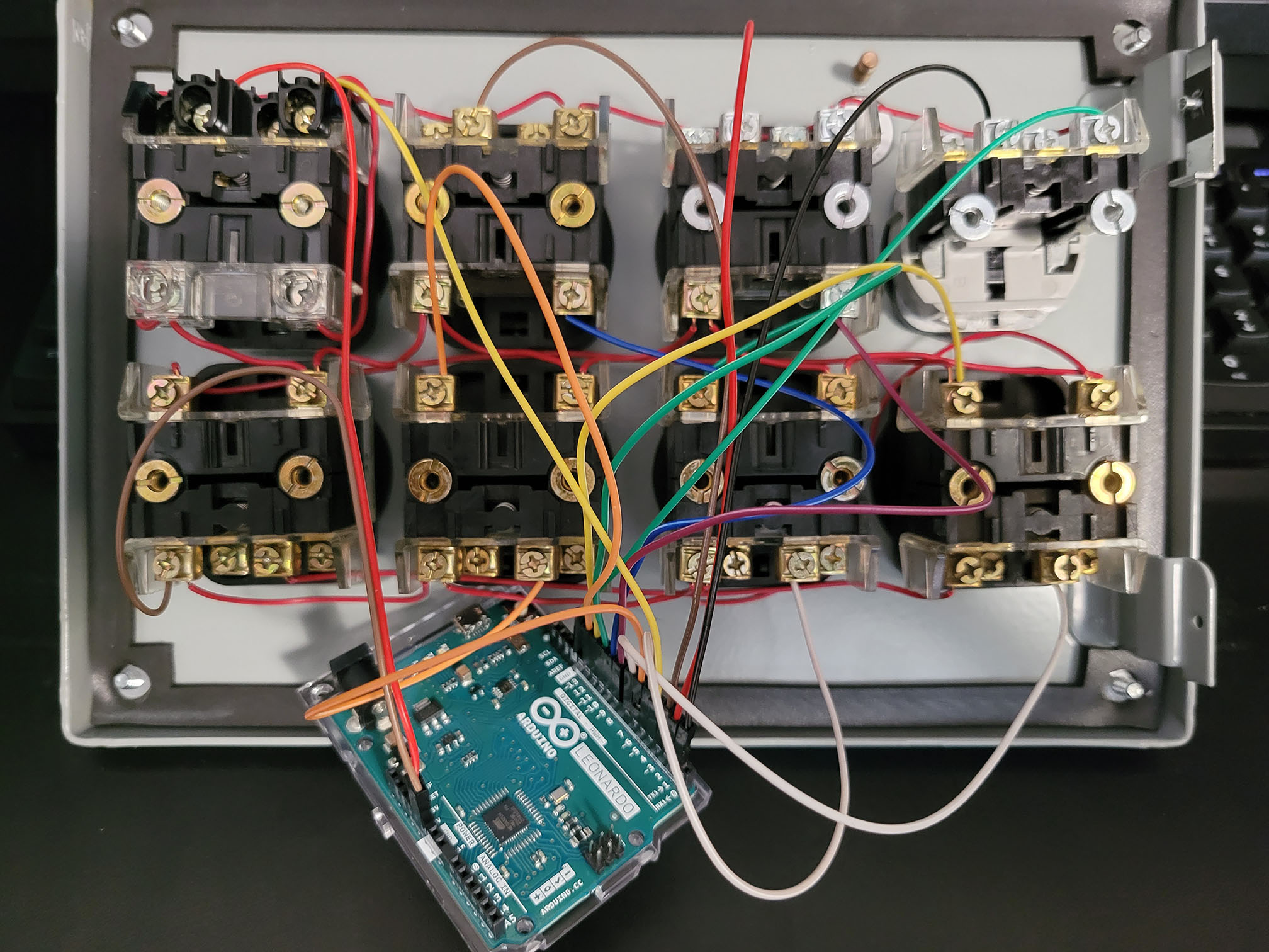
When we use the button all works fine but about 25% of the time when its released the emergency stop message on screen clears and then immediately reappears with the e-stop button in the out position. We have to press and release it a few times until it is in the e-stop off state and the button is in the out position. any help would be appreciated.
That said my grandson still loves the control panel.
Ahart084 31. März 2023 um 12:10 
Where did you buy the buttons
Theme Park Jake UK_YT 19. Jan. 2023 um 10:40 
where caan we by it from
Waldo Lahr 25. Dez. 2022 um 20:43 
and is there any way to make the LEDs go a little dimmer for night time?
Waldo Lahr 25. Dez. 2022 um 20:28 
Alright Ive got it working but is there a way to have the Estop light blink as well as it normally does
Waldo Lahr 2. Dez. 2022 um 10:16 
Does this have to be done with an arduino leonardo or can it be done with an UNO
Mahomey15 8. Nov. 2022 um 10:56 
do you happen to sell these kind off panels? lol
Jurrut 4. Okt. 2022 um 0:59 
Wow, amazing you put the time in to make this tutorial, i've build a big panel few years ago and had to figure out everything myself. Super awesome man, love this!