VRChat
132 avaliações
Create Your First VRChat World
Por Iconoclass
Video version: https://youtube.com/playlist?list=PLPdWkxUSZ65Fp6ICrU7mIq1znAfPwMhNZ

This is the script of a video tutorial series about how to create your first VRChat World using a Unity-only workflow.

This is a project-based course which will end with having a made a unique room and understanding the basics of world creation, such as using Unity and the VRChat SDK, constructing unique geometry with Probuilder, materials and PBR textures, lighting and lightmapping, the asset store and external models and prefabs, World Space UI, Udon, pickupabbles, and Quest compatibility.

6
2
   
Premiar
+ favoritos
Nos favoritos
- favoritos
Introduction to Unity and VRChat Creator Companion

Have you ever wanted to make your own VRChat world but never knew how to start?

Creating an interior in Unity isn’t as hard as you might think!

This beginner course covers everything one should need to know when building a scene, including many best practices. It will be accessible to everyone, including those who have never touched 3D before. We will only be using one software: Unity; this way, you will be able to create scenes fast and efficiently without having to worry about learning or exporting from completely different software such as Blender.

First you have to install the Unity hub, which makes it easy to work with multiple versions of Unity; so when it inevitably updates, the hub makes it easier to download new versions and upgrade or migrate projects. It is also a requirement for creating VRChat projects.

If you’re just using Unity without VRChat, it’s preferable to download the latest LTS version of Unity. Otherwise, skip that and download the VRChat Creator Companion (either the download page after you login to the VRChat website or from the direct link in the description), which will install the correct version of Unity for you if you have the Unity Hub installed.

In the Unity Hub you’ll need to log into your Unity account, or create one if you don’t have one already. You need a license to use the software but the personal license is free and perpetual. If you’re having trouble with this part, then in the preferences of Unity Hub go to Licenses to fix it. I only have a professional license because I’m using the student version of Unity.

If you’re making a VRChat project, the first thing you need is (not a Steam or Oculus account but) a VRChat account of at least New User rank, the blue one, otherwise you won’t be able to upload anything!

After you’ve gotten the Unity Hub and Creator Companion installed, create a new UdonSharp project. This is a world project that allows for C# scripts that use VRChat’s Udon programming language. Even if you’re not gonna touch it yourself, it will allow you to import a bunch of cool toys the community has created; I'll touch on that in a future video.

Here’s a tip: I recommend putting all of your Unity projects in a folder on your larger hard drive if you have multiple, because they can get pretty big!

Once all that is finished, Unity will take a bit to set everything up and then it will open! You should now see the default layout of Unity when you first create a project.

If you want to change Unity between light and dark modes, you can go to Edit>Preferences>General>Editor Theme.

The largest and most prominent window is the scene view; this is a 3D view of your Unity scene. You can use the mouse wheel to zoom in and out. You can use the middle mouse button to pan (or press Q to use the left mouse button instead), and if you hold ALT and left click you can pivot. You can look around by holding the right mouse button and moving your mouse, and while holding, you can also navigate the scene by using the WASD keys, as well as E and Q for ascending and descending.

There should be two objects in the default scene. You can see them in the Hierarchy tab, which is on the left side of the screen by default. If you click on the Main Camera, it will highlight in the editor, a 3-axis gizmo will appear on the object in the scene tab, and information will appear in the rightmost tab, the Inspector. The inspector shows all the information of an object, and each collapsable section is called a component. Every object will have a transform component, which denotes its X Y and Z position, rotation and scale. If you edit the value in the Inspector, the object updates in the Scene view, and vice versa.

Understanding gameobjects is key to understanding Unity. In Unity, everything is a gameobject, and every gameobject can be filled with components to make things happen. Put another way, gameobjects are essentially just containers for different components which can actually do things.
For example, the main camera is not a camera object; it is a gameobject with a camera component. The directional light is not a light object; it is a gameobject with a light component. A character in a video game is not a character object but a gameobject with a skinned mesh renderer component and a character controller component and a bunch of other components and scripts that make it behave like a playable video game character.
Only when you start to think in components can you truly master Unity.

At the bottom of the screen should be the Project view, which shows all of the game assets in the project, many of which can be dragged into the scene.

Unity scenes are like separate levels or worlds: we can create multiple different scenes in a single Unity project but a VRChat world is confined to a single scene.

You can rearrange these panels however you want. For the sake of conformity and ease of learning, I will be keeping the default layout for this series unless I explicitly open a new tab required for the course, which I will make clear. If you ever want to reset to the default layout, you can simply click the dropdown in the top right corner which should say Layout and select Default, or Window>Layouts>Default.

Now we will set up a test scene. First, we need to add a ground plane for the player to stand on. To add an object, go to the Hierarchy, right click and select 3D object>Plane (alternatively you can use the GameObject menu up top). Press F in the Scene tab with the object selected to snap to it. By default, there should be a gizmo on it in the center of the object that has 3 arrows; you can change between the gizmos with the keys W, E, R, T and Y. We want this plane to be in the center of our scene, also called the origin. To do this, make sure the plane is selected, go to the Inspector, and under the Transform component, click the 3 vertical dots, and click reset. This will reset the XYZ position and rotation of the object to 0,0,0 and the scale to 1,1,1.

If you are just making an environment in Unity and not VRChat, you can import and drag in your character controller of choice, such as Unity’s first person controller template.

The rest of this lesson will be to ensure that it’s possible to upload working worlds to VRChat.

If you made this project with the VRChat creator companion then you will see a menu in the menu bar called VRChat SDK. Before touching that go to the Project tab, instead of assets, click right below it where it says “packages”, click the search bar and type “VRCWorld”.
REMEMBER! This is in PACKAGES, not ASSETS!
Drag VRCWorld.prefab into the Hierarchy. Reset the transform to the world origin if it isn’t there already.

Now, go to VRChat SDK>Show Control Panel, and a new window should pop up, which you can dock if you like. Log in and then select the build tab.

Under Local Testing, check force non VR. VRChat should launch, and if everything goes well then you should spawn in the scene on top of the plane!

I would recommend closing the VRCSDK window when not in use, as it has been known to slow Unity down. If the window is undocked, you can close it by clicking the x at the top right corner, or you can right click on the tab and select Close Tab.

VRWorldToolkit gives us a bunch of tools to help make our world more optimized and ensure it isn’t broken; import it from the VRChat Creator Companion.

If you need help throughout this series, I would recommend asking in Unity’s forums or the official VRChat Discord as you’re way more likely to get a response (if you ask nicely and post relevant screenshots). Besides, the comments section isn’t designed for answering technical questions.

That’s it for this lesson, in the next one we’ll start building our room!
Modeling

In this lesson, we will build the geometry of our room!

There’s something quick we should get out of the way first: look at the bottom right corner of the screen to make sure auto generate lighting is off. If it's on, click it and in the new window at the bottom where it says auto-generate, uncheck the box, then close the window.

Before we start using Probuilder, there are some settings that should be configured first. Go to Edit>Preferences and then click Probuilder. There are some changes I’d like you to make here from the default settings, and for the sake of time and not having to explain things that many may not understand, I’ll just rapid fire them.

Enable Show Action Notifications
Enable Auto Resize Colliders
Change Static Editor Flags to Everything
Change Collider type to Box Collider

Now you can close the preferences window and open the Probuilder window by going to Tools>Probuilder>Probuilder Window. Progrids should already be in the top left corner, but if it’s not you can go to Tools>Progrids>Progrids Window. You can dock the Probuilder tab just like any other. You can also switch between the icon view if you prefer by right clicking the tab, and selecting Icon mode or Text mode.

Now that that’s done, let’s create our first Probuilder object! Click new shape, select cube, and confirm. You will now see that a cube appears in the scene! If you click the Probuilder icons in the scene view, you will see that on the cube appear vertices, edges, and faces: these are the fundamentals that make up the geometry of all 3D models. If you click on any of them you will be able to move them around in the scene view, and they will snap to the grid set by Progrids: you can increase or decrease the size of the grid by pressing + or _ on the keyboard, and reset the grid to 1 square meter by pressing 0.

We want to make a room, so let’s make a floor. Click new shape, select plane, change the axis to be up, and set the length to be 6 and the width to be 5 and then click build. Reset the transform so that it is at the origin.

Now, decrease the grid size so it is about 0.125m. Add a cube with the hotkey Ctrl+K. Then go into face mode (the hotkey is K), select a side face, and scale it down so that the mesh is 0.125m thick horizontally. Now drag it out so that the mesh is the same length as the floor. You can see the dimensions of your Probuilder object by looking at the Probuilder script component in the inspector. The average height of a room is about 2.4m-2.5m, so let’s make it 2.5m tall to snap easily with Progrids. Press ctrl+d to duplicate the wall and drag it over to the other side of the plane. Now press ctrl+k to add a cube and repeat the process to create walls for the remaining sides of the plane, and finally add a ceiling.

You’ve now created a box! But it doesn’t look very much like a room. The biggest thing it’s missing is a window! To make a window, select one of the walls, go into edge select mode and with one of the edges selected press alt+u to add an edge loop. This will add a new loop of edges bisecting your mesh perpendicular to the edge you selected. Your edge loop should be selected after you create it, so drag it out of the way and create 3 more to make a cutout for the window.

Now select the two faces where the window is going to be and press backspace to delete them (don’t press delete; it will delete the entire object!). Now select the edge ring where one of the faces used to be, hold shift and use the gizmo arrows to extrude new faces to bridge the two holes.

There’s a problem: the faces are not actually connected to each other. To fix this, go into vertex select mode and press ctrl+a to select all of the vertices of the mesh, and in the Probuilder tab, click weld vertices. This will merge vertices that occupy the same position in space, also known as overlapping vertices.

To add windows, we’re going to add a cube and just add loop cuts and extrude them inwards to make a window. Now you’re getting the hang of 3D modeling!

If you select vertex colors in the Probuilder tab, you can set faces to a vertex color, which can help with visualization and you can later set those vertex colors to actual materials.

We now have the basic geometry of our room. In the next lesson we will learn about bringing our surfaces to life with materials and textures.
Textures and Materials

Now that we have our geometry, it’s time to apply some detail to the surfaces. The way this is done is through materials. Materials can be applied to the faces of geometry and combine a shader and one or multiple textures. To create a material, right click in the project tab and select Create>Material. The default shader is the standard shader, which is a physically based, or PBR shader.

Before we get too much into that, we should set up post processing in our scene. This can very easily be done with VRWorldToolkit. At the top menu bar, go to VRWorld Toolkit>Post Processing>Setup Post Processing and click OK. The defaults should be ideal but if you want to adjust them I would recommend first reading this guide by silent[vrclibrary.com].

I want you to go to this website, ambientCG[ambientcg.com], and pick a wood floor that you would like to see in your room. When you find one you like, check the dimensions (we’ll need these for later), MAKE SURE THE DIMENSIONS ARE THE SAME (not that non-square textures can’t be used in Unity, but they require more steps, are less optimized and don’t compress as well) download 1K PNG, extract, and import into Unity by creating a new folder labeled “_materials" in the project tab (right click>Create>Folder) and dragging in the folder.

This is going to be the most theory intensive lesson because the knowledge of how PBR shaders work is necessary to make correct, good looking materials.

Having a single PBR shader ensures that all materials have consistent shading applied to them, just like in real life. PBR is based on real physical principles, so to understand PBR, you must understand how light interacts with surfaces in the real world. If we drag our material onto the floor we made in the last lesson, we can follow along to see how Unity's standard shader incorporates these principles.

When light hits a surface, some of that light is reflected. Naturally, some light will be absorbed by the materials, but the reflected light is what allows them to be visible. The wavelengths that are absorbed, and, more importantly, the ones that are not, is what gives a surface its color. You can set a base color by clicking on the color picker of the albedo (also referred to as diffuse or base color).

In the color picker window, at the bottom you’ll see the red, green and blue channels. Above that you’ll see the color picker UI, where up and down controls value, left and right saturation, and the wheel around it controls hue. However, this setup is deceiving, because as you increase saturation, value is decreased. And even more confusing, the amount of value decrease varies depending on the hue, with yellow being the brightest hue and blue being the darkest. I’ll link to a video that covers this in more detail but it is something to keep in mind.

The next parameter is specularity, which determines the way light is reflected off of a surface. A 100% specular surface would reflect all of the light rays that hit it at the same angle. At the opposite end of the spectrum is diffuse reflection, where light bounces around inside a material before being reflected in a random direction.

If you click the shader dropdown, you’ll see that there is a standard shader, and a standard (specular) shader. These are two different ways of thinking about PBR because metals are distinct from non-metals (aka dielectrics). Dielectrics typically don’t have a specular component, while metals typically don’t have a diffuse component (exceptions would be imperfections like rust or dirt). The specular workflow gives the artist more control but also allows for the creation of materials that aren’t physically possible. The metallic workflow is therefore generally easier and more intuitive; I would recommend using it over the Specular variant unless your material comes with a specular map.

Now for the other slider you see on the Standard shader: smoothness; this controls the clarity of the reflection. Many materials, like a lot of metals, can be quite reflective but that reflection can still be blurry. This is due to the many micro imperfections on the surface invisible to the naked eye but still affect the angle at which rays of light are reflected (In other programs this gloss or its inverse, roughness).

Another key component of PBR is fresnel, which is applied automatically; essentially, a surface is more reflective when viewed at more intense angles. Additionally, with transparent surfaces, like water on a lake, they are at their most transmissive when viewed perpendicular to the surface and at their most reflective when viewed parallel to the surface. You can easily see fresnel on spherical material previews.

Now let’s put the albedo map for our wood floor into the correct slot in our material! You should now see how the texture is tiled across the surface, but if we bring in a 2m tall capsule for player reference, the planks look too small. So to get the correct tiling scale we have to take the dimensions of the texture (in meters) from the website we got it from, whip out our calculator, and divide 1 by those dimensions. The result is what we plug into the X and Y tiling slots in the material, and now it’s the correct scale.

If you look around for textures, you will see diffuse and albedo, which are both supposed to go into the base color slot. The difference between these two similar texture types is that diffuse textures have directionless shading (like because of crevices where it’s harder for light to reach), while albedo textures have all their shading information removed and put into an ambient occlusion, or AO map. The advantage of this is that the material can react to changes in lighting, for example shining a flashlight against it.

Let’s plug in the AO map to our material! For it to display correctly, click on the texture in the project tab and in the inspector uncheck where it says sRGB (Color texture), since this is a grayscale texture.

Most every surface exhibits details too small to reasonably recreate with geometry. This is where the normal map comes in. Place it into the appropriate slot, click the Fix Now button that appears and now you should see that the material now really “pops”. What a normal map does is change the angle at which light is reflected for each pixel in the texture, also called a texel.

(Each pixel in the normal map represents a vector, where red is horizontal, green is vertical and blue is depth. The “default” blueish purple in a normal map is 50% red, 50% green, and 100% blue, which indicates no change in lighting angle of the corresponding surface.)

Heightmaps are used to fake depth in a material. This should also be set to non sRGB like the AO map. When we apply it we should see the change in our material but it may look a bit off. That’s because in Unity they are approximated by using a technique called parallax mapping, but it breaks when viewed at sharp angles. Typically I don’t set the intensity very high, either the default 0.02 or lower.
Textures and Materials (cont.)
We talked a lot about reflection, and as you should see the reflection of the wood floor doesn’t look very accurate. It looks like it’s reflecting the sky! That’s because the reflection in objects is set to the skybox as the default. To change this, create a reflection probe by right clicking in the hierarchy and going to Lighting>Reflection Probe.

A reflection probe is essentially a 360 camera, capturing a spherical view of its surroundings. The resulting image is called a cubemap, and is used for the reflections in objects.

Place the reflection probe in the middle of the room. Under the reflection probe component in the inspector window, there should be two buttons, click on the left one first. This is the bounds, and the objects inside it will have their reflections affected by the probe. The right is the probe origin, or where the reflection probe will capture from.

Click on bake. We should now see the reflection in the wood. But if we move the camera, the reflection doesn’t move. This is because by default the cubemap is projected as if it is from an infinite distance away, which is great for outdoor areas where there won’t be visible parallax. But for indoor areas this means the reflection will look off if the camera or player view is not at the origin of the reflection probe. Let’s turn on box projection for the reflection probe. What box projection does is project the cubemap to the bounds of the reflection probe, which simulates parallax but also makes clear seams in the projection. This is the ideal setting for indoor spaces.

Now let’s make the material for our windows! Create a new material, name it glass, and drag it onto the window panes. Change the rendering mode to transparent, select the albedo color window and under the RGBA channels, decrease the A channel to 0. The A channel stands for alpha and it controls transparency. Now increase the smoothness to the maximum. Now we have a window that we can see through! Note that if you increase the metallic or specular the transparency decreases. Remember that increasing the specularity not only decreases the base color, it also decreases transparency.

The next important concept to understand is that of material slots. Each polygon is assigned a material, and material slots are a part of the mesh. You can see the assigned materials at the bottom of the inspector window when you click on the object.

We should always compress the textures in our world because they are going to be downloaded by every person who visits the world. To do this, click on the texture file in the inspector and check “crunch compression”. Your textures will now boast a much smaller file size, at the expense of compression artifacts (but no one is going to notice or care). Then click on the Android icon and check “override Android settings”. Then under format, click RGBA Compressed ASTC 6x6 block (this compression algorithm will ensure our textures do not look awful on Quest. Alternatively, you could switch to 4x4 block for better compression but with a higher file size). We should also probably reduce the max texture size on both platforms; this will also have the largest impact on the world’s download size.

There are a couple of other settings we should change. Under Advanced, check Streaming Mip Maps (required for VRChat), change the filter to Trilinear and the Aniso level to 8. Now click the sliders icon in the top right to the inspector (in between the ? bubble and the 3 vertical dots) to create a preset. This way every texture you import from now on will take the settings from this preset (except for those imported from a UnityPackage).

You can also go into VRWorldToolkit>Quick Functions>Mass Texture Importer to change all the textures in the Scene en masse. After a world build you can go into VRWorld Toolkit>World Debugger>Build Report to see all the assets in the world sorted by largest file size.

Unfortunately, Unity’s Standard shader doesn’t support plugging in roughness maps as is. These are very useful as they give varying smoothness throughout the material which adds realism (like a wet road with puddles, the puddles would be smooth while the road wouldn’t be). Unity only supports using smoothness maps (aka gloss maps, the inverse of a roughness map) as the alpha channel of the metallic or albedo texture. There are several ways to implement roughness maps:
  • The easiest way would be to use a different shader, like Autodesk Interactive
  • Use an add-on like SmartTexture[github.com] to pack the roughness map into the albedo or metallic texture, check invert color and use luminance (it has crashed when I used it so don't forget to save!!)
  • Use image editing software like GIMP to create an alpha channel and layer mask for the albedo or metallic texture, invert the roughness map, copy paste it as the alpha and export

This wood pattern texture is a good example of when smoothness maps make a difference; notice how the nails are very specular and have high smoothness while the wood has little specular and varied mid-smoothness that match with the grains.

UV window and UV stitching
Click on the UV editor in the Probuilder tab. UV coordinates is what tells the mesh how to project the textures onto the faces. The U and V are the 2D axes of the UV space, since X, Y, Z and W are already taken by the 3D space.

We won’t get much into UV editing in this course because Probuilder does most of that for you, but the most useful thing to know is how to stitch UVs. To do that, with the UV window open, click on a face in the scene view and then hold shift and click another connecting face. The UVs will now stitch, and make the texture continue without a seam between the faces.

https://youtu.be/bigj13SU1rs
https://youtu.be/d3_2h4cN4cY

Now you can find some other textures to finish the room, and we can move onto the next stage, lighting!
Lighting (for static objects)

Welcome back to the 4th lesson in this tutorial series where we will create proper lighting for our scene!

Something I should have mentioned last episode was finding reference photos to influence your choice of textures. As a beginner you shouldn’t be trying to create your own styles but instead try to replicate styles that already work. For example, in my world Room at Sea, I looked at beach houses and found elements from the references that I liked that I wanted to incorporate into my own scene, those being: color pallet; a lot of whites and grays, some poignant blacks and a light blue and beige color combination.
When making your own room, try not to clash styles and stick with just one, at least for now; for example, instead of clashing New York interior brick with Floridian spanish-influenced architecture, just stick with one or the other, and focus on the elements of that style which really work and give you the feeling or vibe you want to have when being in that space. For this tutorial series I am going to go with a minimalistic Scandinavian apartment style since it makes sense for the small room we are creating and it's relatively easy to make in 3D because of its simplicity.

When looking for references I would recommend image based browsing sites like Pinterest[www.pinterest.com] or Houzz[www.houzz.com]; both make it easy to search for similar looking interiors and save images you like. And as you should notice by looking at Scandinavian apartments there are a few things that should jump out to you that makes the style: minimalism, in geometry of the interior structure and objects, and limited color, with most of the scene being grayscale. This analysis is only scratching the surface of visual composition; if you want to learn more about it I would recommend watching Blender Guru’s videos on topics like color, composition, and lighting.

https://youtu.be/Qj1FK8n7WgY
https://youtu.be/O8i7OKbWmRM
https://youtube.com/playlist?list=PLjEaoINr3zgH9vCr47kSS5W8PEJBNIiwK

Additional software like https://www.pureref.com/ and https://allusion-app.github.io/ can be used for viewing and browsing through reference images saved to your computer.

There’s also some special techniques you can use to easily modify materials more to your liking. I found a plain plaster texture on https://textures.com/download/PBR0088/133122 (which requires an account) but it was a little dark for my liking. For this material, since there was little detail in the albedo texture and I didn’t really care for it anyway, I can remove the albedo texture from its slot and instead choose whatever color I want for the paint while still retaining the detail from all the other PBR maps.
If you don’t want the material to look as bumpy, you can decrease the strength of the normal map.
And one last thing, you actually don’t need to open a separate calculator to get the correct tiling because you can just do the math inside the box.

Now onto lighting. This in combination with our material choice is what visually makes our scene. What we’re going to do is create baked lighting; this means that lighting will be precalculated on your computer so it doesn’t have to be calculated on the player’s, drastically increasing performance and lighting quality. It does this by calculating the lighting for all the static objects and “baking” the shading into a lightmap. Dynamic objects (like avatars) are lit by using lighting probes.

First, make sure that all the static objects in the scene are marked as “static” in the inspector tab.

Set all the lights in the scene to Baked.

Next, open the lighting tab by clicking on auto-generate lighting in the bottom right corner or by going to Window>Rendering>Lighting. It might pop up as an undocked tab, but you can dock it wherever you like. Personally, I like to put it in the same space as the inspector on the right and then switch between the two.


Under Realtime Lighting, turn realtime global illumination off. I won’t get into it here since this is supposed to be a beginner tutorial series but unless you know what you’re doing with it you should have it disabled.

Under Mixed Lighting, with Baked Global Illumination on, set the Lighting Mode to Baked Indirect. This means we won’t have realtime lighting for our dynamic objects but this is what we want because realtime lighting has a heavy performance cost.

Now we get to the lightmapping settings. The first option is the lightmapper, change it to Progressive GPU. As of recording the GPU lightmapper is still in Preview which means it is not production ready; if it gives you errors or glitches you can switch to Progressive CPU but for quick iteration GPU lightmappers are much faster than CPU ones.

For the lightmap resolution, rather than simply explaining everything it would be best to get a visualization of it in your own scene. In the Scene view, at the top right, click the dropdown where it says Shaded and go down to Baked Lightmap. Here you will see a visualization of the lightmap texels in your scene. What the lightmapper does is calculate the lighting for each texel and then puts that into a pixel in the lightmap. Don’t worry, we’ll get to see the lightmap once it’s baked so you can get a better visualization.

The Lightmap Resolution is in texels per unit. If you drag left and right to decrease and increase the value, you can see that the amount of texels in the scene changes. This value essentially means how much lighting resolution we want to give to our objects, where higher resolution means higher quality and less pixelation, but also means that our lightmaps will take up more storage and take longer to bake. Right now, let’s set it to 20 so that it will bake faster, and we can increase it before our final bake.
In the rendering component of an object you can adjust its lightmap scale.

Other important settings include:
  • Prioritize view: if enabled it will prioritize baking in the view of the scene tab first.
  • Light bounces: the more bounces, the more realistic. Outdoor scenes may not need as many bounces, indoor scenes will greatly benefit from them. Noticeably increases bake times so probably best to keep it around 2 until the final bake where you can increase the bounces to the maximum.
  • Lightmap size: this is just the max lightmap size, set this to the largest (it will increase performance because there will be fewer lightmaps)
  • Ambient Occlusion: turn this on for realistic ambient shadows

    With it all set up, click generate lighting at the bottom, and wait. For larger scenes this can take a while but since our scene is so small and we set the lightmapper to use the GPU it shouldn’t take too long. If you switch between Baked Lightmap and Shaded views in the scene view, you should now be able to get a better idea of how baked lighting works.
    From here you can tweak the lighting as you like before the next bake. And with the Progressive lightmapper’s prioritize view, you get a noisy preview of how the result will look as it is baking.

    In a room, it would make sense to have a light in it. If you right click in the Hierarchy, go under Lighting, you will see the 4 different types of lighting in Unity:
    1. Directional light: essentially the sun. The rays have infinite distance, so shadows cast with this light will always be parallel, and its position is irrelevant, only its rotation matters. It comes by default with every new scene and there should be a maximum of one per scene.
    2. Point light: a light source with a finite range in all directions
    3. Spot light: has a finite range within a cone shape with an angle defined in degrees between 0-180
    4. Area light: a flat 2D light source over an area. Baked only, no realtime.

    Point light seems to make the most sense for our scene. Add a new point light and put it near the ceiling. DO NOT put it in the ceiling!
Lighting (for dynamic objects)
So now we have lighting for the static objects, but what about the dynamic ones? Right click on the Hierarchy, Lighting>Light Probe Group. It should now appear in your scene as a web of 8 spheres. Each of these spheres is a probe, and for each probe, Unity calculates how it would be shaded at that point in space. As dynamic objects move through the light probes, they blend the lighting data of the nearest ones.

If you click on the light probe group, you should see in the inspector that you can press a button to toggle probe editing mode. From here you can click on and move individual probes, shift click them to add them to the selection, and ctrl+d to duplicate them. Now the objective is to fill our room with light probes. But how should we fill it? The easiest way would be to fill our room with probes like a 3D grid, but then we wouldn’t get the most accurate lighting. The optimal way to place light probes is to place one wherever there is a change in lighting!

Let’s go place them in the obvious spots, like wherever there is a clear light cutoff, like sunlight hitting the floor. Just above the floor, place light probes in the four corners of the sunlight, and then in the four corners just out of the sunlight. Do the same but at the window. Now place light probes around other lights in the scene, and at the edges of any shadows.

At the top of the lighting window you’ll notice environment lighting, where it says Skybox. This is what will determine the cubemap that gets used for the fallback reflections of the scene, or when an object is outside the bounds of a reflection probe. Right now Unity will bake a cubemap of our skybox, which is not what we want because the skybox won’t be a proper reflection of our scene if everything is going to be inside our room. Click “Skybox” and set it to custom. Then in the project tab navigate to the reflection probe (which should be under Scenes>Scene name) and drag it into the slot.

One last important thing to mention is Occlusion Culling, which will increase the performance of your world by not rendering objects that aren’t in the player’s view. Go to Window>Rendering>Occlusion Culling and click Bake. If you click Visualization at the top of the tab, select your camera, move it around and you can see how Unity will now draw the scene.

To get better occlusion culling right click in the hierarchy>lighting>occlusion area and then fit this volume to the places in the scene where it is possible for the player to be.

It’s best to clear occlusion culling data while you are still editing static objects in the scene and then bake before uploading. If it’s not working correctly (objects are disappearing when they should still be in view) either re-bake or tweak the settings under Bake in the Occlusion tab. Note that occlusion culling only affects the visual rendering of objects, so processing of them will still occur even when out of view!

Tweak the settings of the lights, bake again at higher settings, and your room should now have beautiful and performant baked lighting! Next lesson will go over how to add external models to the scene.
External Assets and Prefabs

Again I have to backtrack at the first part of the lesson because it turns out a topic I chose not to cover last episode is actually of importance because our scene’s lighting comes primarily from the environment (indirectly) rather than from a light source component. If you look at some parts of the wall you may see that some of them look a little blotchy. This is being caused by both the indirect and environment samples and by the filtering in the lighting tab.

Rather than simply explain it I feel it is best to show you to truly understand how the technology works. Slight trigger warning, I’m going to disable the filtering and the scene is going to look very noisy and ugly. For most of you it will be unpleasant to look at but if it disturbs you in any way you can skip ahead ten seconds. This is what the lighting looks like with the filtering turned off.

The reason it looks so noisy is because of how ray tracing works; essentially a higher sample count means less noise. However, under filtering>advanced, you can see that there are denoising options. These reduce noise by using AI denoising algorithms. By increasing the number of samples, the baked result has less noise, and there is less blotchiness in the bake, at the expense of render time. From what I could read and from my testing, it appears that the environment samples is bounded by the indirect samples, so I’m going to increase both by about fourfold to 2000. If you are in a state where you are baking a lot just to preview your lighting you will probably want to decrease this until your final bake.

In scenes where the primary light sources are from light components, this typically isn’t something to worry about. It’s only because our primary light source is the environment that this becomes something worth considering. Direct lighting will always be far more accurate, far less noisy and take far less time to bake than indirect lighting.

Onto the main topic of this lesson. For those who don’t know, an asset is just anything that goes into a 3D scene. There are websites you can download 3D assets from (always make sure you are legally allowed to use them) but the place I would typically check first is the Unity asset store. You can either browse it from inside Unity (windows>Asset Store), but the in-editor browser is slow, so I recommend using a dedicated browser. Go to the following link: https://assetstore.unity.com/

The convenient thing about the Asset store is that the assets are made specifically for Unity. I say this for two big reasons: one, many of the assets are simply drag and drop and don’t require much additional setup or configuration (if any). Two, many 3D models that you find on other websites will have polygon counts that would be absurd for VR games (>20,000 polygons for simple objects). This is because they are not intended for games but for movies or 3D renders which don’t share the same technical limitations. The recommended maximum polygon count for Quest worlds is 50,000 triangles according to the official VRChat documentation, and even if you don’t plan on uploading to Quest I would still keep a soft polygon limit in mind. Saving a few dozen here or there would be negligible for performance, but it wouldn’t make sense to have a single object with 50,000. If you still want to use that object and it doesn’t come in a low-poly version I would recommend taking it into Blender and either using the decimate modifier (which is quick and dirty) or baking to lowpoly.

The first asset we should search for is a proper skybox. Just type skybox into the search bar, check free assets only, and I’m going to use this allsky free pack for this tutorial because it is free, popular, and high quality. After it is in your asset library, click open in Unity which will take you to the package manager. You can also open it by going to Window>Package Manager and then making sure the dropdown at the top left next to the + dropdown is set to “My Assets”. Now click on download and import and they will be in your project. Find the overcast skybox material and drag it onto the skybox in the scene. It looks a little dark so I’m going to increase the exposure to the point that the highlights are not overexposed.

Our room looks kind of barren, why don’t we search for some furniture? Pick out something you like. I’ll search for a sofa. I’ll be using this sofa pack for this tutorial but even if you’re not you can still follow along with your model of choice. Since this is your room I encourage you to make it your own, and that means using modelling, textures, lighting, and assets that fit your scene. That means you shouldn’t put in elements that would clash with each other, and every part should ideally complement every other part.

First, add the model on the page. Download and then import through the package manager. Once imported look for a prefabs folder, click on the one you want, duplicate it, and drag it in the scene.

Before we get into that it’s necessary to know what a prefab is. A prefab is a gameobject with all its components intact. The advantages of working with prefabs is that if you have a lot of the same gameobjects in a project and you want to edit them all at once, you can do so without having to individually edit each one.

Say we want all our windows to be the same. Instead of having to edit each one individually, we can make them a prefab by dragging our parent window object from the Hierarchy into the project tab. You should now see that the object icon in the Hierarchy turns from a hollow gray to a solid blue! You can edit prefabs by double clicking on them in the project tab, or by right clicking the prefab in the hierarchy and clicking open prefab asset, and the scene view will focus on just the prefab. Edits you make from here will apply to all instances of the prefab. Exit out of this view with the arrow at the top left of the scene tab. If you make a change in one of the instances of the prefab you can right click on that parameter in the inspector and click “apply to prefab”. If you want to make one of the instances of the prefab no longer a prefab, you can right click on it in the hierarchy and click unpack prefab. You can also put prefabs inside of prefabs; unpack prefab only unpacks the parent prefab while unpack completely also unpacks any nested prefabs.
External Assets and Prefabs (cont.)
The sofa prefab I got didn’t come with any colliders. Let's add some by double clicking on the prefab in the project tab, going to the gameobject that has the mesh renderer component (so the colliders will conform to the bounds of the mesh when they are first added) and adding box colliders and shape them as a simple boxed version of our mesh. For the colliders for the cushions of the sofa I’m going to make one, click the 3 dots, copy component, and then paste component as new. This way the height of the two colliders will be exactly the same and players won’t notice when walking from one collider to the other.

For complex objects, you could make a simplified collision mesh with probuilder (or blender), make it a child of the model gameobject, and disable its mesh renderer and add a mesh collider component. The primitive collider components are more optimized and reliable so it’s preferable to use a compound of those when possible.

Our sofa is also static, so don’t forget to tick that box.

Let’s add some seats to the sofa. Search for VRCChair, duplicate VRCChair3 and then double click on the newly created VRCChair4. Delete the gameobject with the chair mesh and scale down the collider vertically. Open the sofa prefab, drag in the new VRCChair and place it under where you want there to be a seat. Make it face the correct direction; make sure that the tool handle is set to local rotation, then the blue arrow, the z axis, is forward. Ensure that the top part of the collider is above the collider of the sofa. The seat and exit gameobjects are empty and are only used for the transform where the player will sit and exit; you can adjust them if you like. Duplicate the chair prefab if you want more seats.

There is a VRChat layer called walkthrough, and it allows players to walk through objects that have colliders, while physics objects like pickupables still react to them. Since elevation change can be one of the most disorienting parts of VR, especially for new users, I tend to set many smaller static objects to this layer by default. In a later tutorial, I’ll show how to toggle these objects between the Walkthrough and Default layers.

Also, find the model file for the object in the project view (you can get to this by clicking on the mesh in the mesh renderer component of the object). In the inspector under the model tab, ensure that generate lightmap UVs is checked. You will have to do this for every model you import that is set to be lightmapped (unless it specifically states that it comes with UV2s for lightmapping).

Imported textures are not compressed! Don’t forget to compress them!

Don’t forget to move your light probes so that they are not in places which dynamic objects can’t reach or places where they will be blocked from receiving any light (like inside of objects)!


As for models from other sites, they require more setup than ones from the asset store. Typically there will be a model file and separate texture image files, so you will have to create a new material and plug in the textures yourself. The ideal 3D model format to import into Unity is .fbx, but .obj also works for static meshes. If you are downloading from an external site, make sure it is one of these formats. DO NOT import .blend files into Unity and drag them into your scene, there will likely be issues. And don’t forget to check Generate lightmap UVs if the object is going to be lightmappped!!!

You can use a 360 degree image or an HDRI as your skybox. I’m going to go to a website called polyhaven which has public domain HDRIs. When you find one that you like, download the 2K EXR (both are compatible with Unity but EXR is preferred). Drag into the project window, and it looks like a 2D texture. We want to project this texture like a sphere, hmm, when have we done this before? It sounds kind of similar to the cubemap of the reflection probe. To change the projection of the texture, click on it and in the inspector change the texture type from 2D to Cube. Now you can just drag the texture onto the sky and Unity will create the skybox material for you. You could even combine a higher intensity skybox with a low intensity directional light for artistic effect.

Note that the projection and scale of 360 degree pictures will not look correct as a skybox, and that there will not be any parallax when the player moves. This makes rooftop shots the best 360 images to use since when viewed through a window you naturally wouldn’t see much parallax.

If you want world music or sounds in your world, drag an audio file into your project and then drag it into the scene, and it will automatically come with an audio component. In the inspector click Add Component and search for VRCSpacialAudioSource (which makes the sound work in VRChat). If your sound is world music, you probably don’t want the sound to be coming from a certain point in the world, so go under advanced options and uncheck Enable spacialization.

For better compression, click on the audio file, set the format to Vorbis and drag down the compression slider. If the compression is noticeable you can drag it up until it isn’t.

If your sound is spacialized then having a stereo audio file won’t matter so set it to mono for a reduced file size.

And that’s about it for this episode. This marks the halfway point in the series; the tutorials up until this point were mostly just generally learning the Unity software with an emphasis on interiors. From here on out, the tutorials will mostly be about learning implementations of Unity components specifically for VRChat. In the next lesson, we will go over how to add a mirror and a toggle for that mirror using world space UI.
Mirror Toggles with UI

Let’s get to the moment most of you have been waiting for, adding a mirror! In the project tab, search for mirror. Drag VRCMirror into your scene, rename it to HQ Mirror, then position, rotate, and scale how you want it. If you imported VRWorldToolkit (like you should have in part 1) then you will see a button that says Show Players/World. Click on it, and then under Reflect Layers also enable Pickup and Walkthrough. Now disable the mirror.

OK, we have a mirror, but how do we toggle it on and off? This is where UI comes in. We want to have a toggle we can click, so in the Hierarchy, right click, UI>Toggle. This will spawn a UI toggle parented to a canvas, which is a necessary component to display UI elements; however, we need to fix a few things first. In the Hierarchy, click Canvas, then change its Render Mode to World Space. Under Rect Transform, change the XYZ scale to .001. Then change the layer from UI to Default. Add two components, a box collider and a VRC Ui Shape. Now position it against a wall; turn off progrids so you can position it slightly off of the wall, not inside of it.

In the hierarchy, under Canvas click toggle and set its width to 700 and height to 120 and untick Is On.

In the hierarchy, under toggle click label. Make the text “HQ Mirror Toggle”, change the color to white and increase the font size. You can change the font, and you can even import custom fonts by dragging in a ttf font file from C:/Windows/Fonts. You can also add a shadow by clicking Add Component and searching for it.

Click Background in the hierarchy and change the width and height to 100. Then change the offsets to 50 and -50 to position the checkbox correctly. Then click Checkmark in the hierarchy and change the width and height of that to 100 as well. Finally select the label again and set left to at least 100 (you can use the gizmos to translate UI elements the same as other objects).

Now under toggle, set navigation to None. Click the plus icon at the bottom of the component where it says On Value Changed and drag in the mirror from the hierarchy. Click the dropdown that says No Function and select GameObject>SetActive under dynamic bool.

Duplicate your HQ Mirror, rename it to LQ Mirror, click show players only, and duplicate the button we just created. In the toggle drag in the LQ Mirror in place of the HQ one and change the label to LQ Mirror Toggle.

To ensure that only one mirror is on at a time, add a new slot, drag in the HQ Mirror Toggle, and under the dropdown select Toggle>isOn under static bool and leave the box unchecked. Do the same for the HQ Mirror Toggle, with the LQ Mirror Toggle in the slot. However, if you have a mirror on and want to select a different one, you have to click the button twice, once to turn the current mirror off and another time to turn the desired mirror on.

Press the play button to test this out by using CyanEmu (which you also should have imported in part 1).

If you want to make this UI but using Udon you can check out Vowgan’s video! https://youtu.be/E0D9Z8-HVBI

Move one of the mirrors slightly in front of the other to avoid z-fighting.

If you have a larger world, note that the LQ mirror will render avatars behind it, even if they are through walls. For the sake of performance and privacy it would be wise to position mirrors where they are not going to do this, or even design your spaces where mirrors will go with this in mind.

By the way you’ll probably want to organize your hierarchy at this point. You can essentially use empty gameobjects as folders, but make sure you reset their transform first or else it will mess with the position of the child gameobjects which will mess with progrids! If you forget and don’t reset the transform, drag out all of the child gameobjects, reset the transform and then drag them back in.

A bit of a bonus, I had a question asked in the comments about how to do neon lighting. First add in an object you want to give neon to, so I’ll go into the probuilder window and add a skinny cylinder with no height segments. I’ll extrude it to form it how I want. I can create extrusions and then rotate with a center pivot to create turns in the neon tube. After you finish modeling, create a new material and check the emissive box and set it to baked. Apply it to your object and select the color you want it to emit. Bake and you’re done!

A few tips with this: one, you can enable bezier curves (and booleans!) in probuilder by going to Edit>Preferences>Probuilder>Experimental Features Enabled. However, neither of these work great in probuilder so I would recommend doing them in Blender instead.

Two, make sure the lighting fits your scene. If you are going for a warm or natural look you will want to limit yourself to the colors on the kelvin spectrum. If you are going for an artificial look you can use colors on the full visible light spectrum. This is covered in the Blender Guru lighting course I recommended at the beginning of lesson 4.

That’s it for this lesson. The next one will be a continuation of this one, where I’ll show you how to toggle objects between the default and walkable layers by using UI with Udon!
Collider Toggles with Udon (part 1)

This is a continuation from the last lesson, where we will be making a world space UI button to toggle whether players will collide with certain objects, or more specifically, switch those objects between the walkthrough and default layers.

In the project tab, right click, Create>VRChat>Udon>Udon Graph Program Asset. Rename (right click or F2) this to Collider Toggle. Duplicate one of the toggles and rename the object and the label to colliders. Click the toggle and add an UdonBehavior component and drag in the udon script. At the bottom of the toggle component, click the minus button to remove the old slots, then click the plus icon and drag in the UdonBehavior.

Click the program in the project view, and then press “Open Udon Graph”. The Udon tab should pop up now!

The welcome screen should be the first thing you see. You can change the grid size if you want, I like to set it to 20 but that’s just my preference. Now click Open Collider Toggle, and this is the Udon Graph!

Udon is visual scripting, or essentially code, but visualized as nodes rather than as lines of text. I know the word “coding” scares some people, but it’s probably not as hard as you think. If you never want to touch Udon again after this that’s fine, I’ll be holding your hand through this entire tutorial.

It’s best to first think of how our code would work in a purely logical way, just the steps written in plain English that we can then convert into code.

The prerequisites before our code is run is that all of our objects are on the same layer, and we want to have a list of all the objects we want to toggle.
  1. When the code starts, we want to check the first object to see if it’s on the default layer. (Since all of them are on the same layer it makes sense that we only have to check one)
    1. If it is on the default layer, then it means that all of the other objects are on the default layer too, and we want to switch them to the walkthrough layer.
    2. If it isn’t on the default layer, it means all the objects are on the walkthrough layer and we want to switch them to the default layer.

The first thing we need to create are some variables. Variables are used to store information that can later be referenced or manipulated. There are many types of variables we can create for the many types of data we can use, such as ints which are essentially integers, booleans which are true or false, gameobjects, any type of component among many others. A variable can also be an array, which is a variable composed of multiple variables of the same type. An array is represented with [square brackets] next to the variable type. We can add new variables to our script by clicking the plus in the variables menu in the top left corner.

  1. The first variable we need is an array of gameobjects, the one with the [square brackets]. Rename it to Targets. Click the arrow beside the new variable and check public; this makes our variable accessible outside of our script. If you click on the collider toggle UI button we made you should see it in the inspector. Drag in all of the gameobjects that are to be toggled. Make sure to drag in the gameobject that actually has the colliders on it! Also, child objects are not affected!

  2. The last two variables we need are the layers. Layers in Unity are stored in numerical order and must be referenced by that assigned number. If you click the layer dropdown on any component you can see that the default layer is 0 and the walkthrough layer is layer 17. Add two ints and set one’s default value to 0 and the other to 17. Rename them to defaultLayer and walkthroughLayer.

Now we can start adding in nodes! The first thing you should know about them is that individual nodes represent either data or an operation. Sockets on the left of the node are inputs while those on the right are outputs. I know that coding can be pretty daunting for the complete beginner, but you’ll start to understand some of the basics after this lesson.

Press space in the empty grid for quick search; this is how we can add in new nodes. The first node we need is one that starts the rest of the script. That type of node is called an event, and we want the script to be run when the toggle is pressed, so search for “event custom”. Type “ColliderToggle” into the node’s box. Then in the inspector in the toggle component change “no function” to UdonBehavior.SendCustomEvent(String). Copy and paste “ColliderToggle” into the box.

The next thing we want to check is if the first gameobject of the array is on the default layer. First, click and drag the Targets array variable from the menu in the top left into the grid. This will make a node where we can access our array of gameobjects; however, we only want the first gameobject, not all of them. Drag out from the node, then search for and add “get”. This node allows us to get only one gameobject from our array of gameobjects. Since 0 represents the first thing in the array, just leave that in the box. 0 is typically the starting number for things in programming, not 1.

Now we want to get what layer that gameobject is on. Drag out from the get gameobject, search for layer and choose “get layer”.

Now we have the layer of the first gameobject, as an integer. We want to compare it to the integer representing the default layer, to see if they match. Drag from the get layer and search for equals. Drag the default layer variable into the grid and plug it into the int slot. The equals function is comparing the two integers to see if they are the same. If they are, then the output is true; if not, the output is false.

You might have noticed that before we plugged in the default layer, the value in that input was already zero. We can actually click in the box and set it to anything we want. Since the default layer is a constant (it will always be the same, the number 0), we could have simply not created the default layer int variable at all. The reason I told you to is to show that making constants as variables can make your code easier to read, especially if that constant is used multiple times in the code.

Before we move on, it is best practice to organize our code into groups to make it easier to read. Highlight all the nodes we just created except the Custom Event node, right click and then select “create group”. Now all of those nodes are in a big box. Double click group to rename it to “Is the first gameobject on the default layer?”. You can also right click to create comments. This is often overlooked by beginners but it is a godsend when someone else is trying to interpret your code, or when you are trying to interpret your own code when coming back to it after a long time.
Collider Toggles with Udon (part 2)
All the gameobjects of the array should be on the same layer. If the first gameobject is on the default layer, that means all of the gameobjects in the array are on the default layer and we want to switch all of them to the walkthrough layer. If the first gameobject is on the walkthrough layer then we want to do the opposite.

An “if” in our logic is typically an indicator that we want a branch in our code. Drag out from the equals node and search for branch. Drag the custom event arrow to the left branch arrow.

Let’s start with the true branch first. What we want to do is iterate through all of the objects in our array and change them to the walkthrough layer. If we want to repeat the same code, this is typically an indicator that we want a loop. There is a specific loop we can use for an array called a for loop (or a foreach loop if you’re using UdonSharp!). Search for “For” and add it. Drag the true from the branch into the left arrow of the for loop.

Our array starts at 0, so just leave that input at 0. For the end input we want to get how many objects are in our array. Drag the targets array from the variables menu into the grid. Drag from the node output and search for length. Choose the first one, “get length”, with the lowercase g and 2 separate words. Now drag the output of that into the for loop “end” input. We want the step to be 1 so just leave that.

What the for loop does, essentially, is for each gameobject in the array, execute the body of the code. How many times the code is run is determined by the 3 inputs.


Now that we have the for loop set up, we want to just change the gameobject’s layer from default to walkthrough, from 0 to 17. Drag targets into the grid again. Drag out from the output and search for get. This node will give us only one of the gameobjects in the array. Drag the int index from the for loop into the int input of the get gameobject node. This gets us the specific gameobject at the index that the for loop is at. So if the for loop is at the first index, the get gameobject node will give us the gameobject at the first index in the array.

Drag out from gameobject, search for layer and choose set layer. Drag the walkthroughLayer variable into the grid and connect it to the int value input. Now connect the body arrow from the for loop to the set layer node

And that’s it for the true branch! For each gameobject in the array, that gameobject’s layer will be set to the walkthrough layer! Outline all the code and create a new group, name it set to walkthrough layer.

The false branch is actually really similar. Just select all the nodes from the true branch, press ctrl+d to duplicate them, drag them down and then replace the walkthrough layer with the default layer. Connect the false branch to the for loop, create a new group called “set to default layer”, click compile at the top right of the window and you’re done!


Now just test it using CyanEmu (press play)!

You can use Debug Log to send messages to the console when running a script. This is incredibly helpful for troubleshooting.

I want to stress that I cannot help you in the comments section. For some of you, because you are new to coding and Udon something may go wrong. The comments section is not engineered so I can give you much back-and-forth help. Your best bet is to look at the console for errors if there are any, look them up yourself, use debug log to troubleshoot yourself, and if none of that works then ask in the udon channel of the vrchat official discord[discord.com] (or the udonsharp discord if you are using udonsharp). Again, please do not ask in the comments section. I can’t help you.

There is a simpler way of creating these Udon systems for SDK3 which emulates the way in which Triggers worked in SDK2; it’s called CyanTriggers and this is an extension can be downloaded either from Github for free or from the creator Cyanlazer’s Patreon for the most up to date version. I’m not familiar with either of these and to avoid importing too many external tools which may be subject to change I didn’t cover it. I would recommend Cyantriggers to anyone who doesn’t already know coding and doesn’t want to learn it or to anyone who is more familiar with triggers from SDK2 and wants to use a workflow more similar to that. SDK2 is now deprecated so I would never recommend it to anyone starting a new project.


If you want to create udon programs using more traditional line-by-line C#, you can check out UdonSharp[github.com].

If you want to learn more about coding, specifically C# which Unity and UdonSharp uses, I would recommend checking out the beginner series by Brackey’s. He used to make a lot of really good Unity tutorials so these tutorials have in mind that much of the audience wants to learn the basics of C# so they can program in Unity.


If you want to learn more about coding for VRChat in both Udon and UdonSharp, I would recommend watching Vowgan’s tutorials. These are the coding tutorials that are going to be the most specific to VRChat but I would recommend having a decent grasp on the basics of coding first.


In the next lesson I’ll go over pickupabbles and physics!
Pickupables and Physics

Now what about things that you want to pick up or throw? This, unsurprisingly, requires physics. Don’t worry, you won’t have to do any calculus, this only requires a simple understanding of a few components.

Create a small cube. On that cube, click add component, search for pickup, and click VRCPickup. You should now see that there are two components added, a rigidbody and VRCPickup.

A pickup in VRChat requires 4 components:
  • Rigidbody: this calculates physics
  • Collider: for collisions
  • VRCPickup: so you can grab/use the object in VRChat
  • VRC Object Sync (optional): so the object can be synced between players. Note that each synced object must have an owner, which is why pickupables look fine in your hand but look laggy if they were last held by another player

If you enable Is Kinematic, your object will only be able to be moved by a player interacting with it. It will not collide with other objects (though other objects will collide with it), and will not have physical forces applied to it. This is a popular setting for pillows.

Physics materials give objects more realistic physical properties. You can add them to the colliders of your surfaces and pickupables to make them more believable.

You can use multiple colliders for more accurate collision; for example, for my glass bottles, I start with a box collider, then shrink it on the X and Z axes. Then I add a capsule collider and shrink it on the Y axis until it aligns with the bottle. This allows the bottle to roll but also stand up if placed on its top or bottom. Note that you will only be able to grab the first collider that appears in the inspector.
Video player, Pens and Other Prefabs

I figured I’d dedicate a separate short lesson to VRChat specific prefabs, because there are a few that I know a lot of people want in their worlds.

Many VRChat prefabs can be found on the VRCPrefabs database. Note that SDK2 prefabs will not work in our SDK3 world, only Udon Prefabs will work.

Many prefabs require UdonSharp to work; this complies C# code to Udon. You don’t need to know how it works, just make sure you import it before importing an Udon prefab that requires it.

One of the most popular features of small worlds is a video player. One of the most popular of these is Merlin’s UdonSharp player (which we will be using), but some other ones are VRCUdon’s and ProTV. Technically all of these are supported on Quest HOWEVER YouTube and Twitch URLs do not work, more info in a post in the description.

First, we need to import UdonSharp. Grab the unitypackage from the Github page under releases for both UdonSharp and UsharpVideo. There should be a videoplayer prefab in the UsharpVideo folder in the project, drag that into the scene, unpack and you’re done!

You can change some options on the player, like whether control is locked to the master of the world or whether anyone can paste video links.

You can change the UI style by going to the ControlsUI gameobject in the prefab, clicking on the style file and draggin in a different one from the folder or you can make your own.

You can add URLs for the Videoplayer to play by default by clicking the + icon under “Default Playlist URLs” on the root gameobject of the prefab.

The prefab comes with audio settings pre-setup but you may want to change them. Some of the audio settings are pretty self-explanatory or as always you can click the circle with the ? to go to the documentation page; however some are a little confusing so I’ll go over them. The spatial blend controls how much the audio source is handled by the 3D engine; so if it is set all the way to the left, to 2D, all of the settings under the 3D settings dropdown are ignored and the sound is always omnipresent.

Spread controls where the sound is coming from. If it is set to 0, then it will sound like the sound is coming from the audio source; if it is set to 360 then the sound will come from the direction opposite of the source.

Personally for video players I like to set the spread to 180 so it won’t sound any different when you move your head (like an omnipresent sound) but still set the spatial blend to 3D, the falloff to logarithmic and the min distance to something like 4, at least in larger worlds with at least a few rooms, so that if players walk further away from the video player the sound will start to fall off. Also if you do this make sure you set the stream audio source to stereo mix and disable the other stream audio source channel gameobject – then don’t forget to apply the same settings to the video audio source!

If you’re just making a one room world you can disable the 3D spatialization settings entirely by unchecking the “Enable Spatialization ” box under advanced settings in the VRC Spacial Audio Source component.

Prefabs with Udon elements can cause conflicts, so it’s best to unpack your prefabs in your scene to ensure they work properly. You can right click on the prefab in the hierarchy and click unpack prefab; this will make your object no longer a prefab.

Another popular prefab is Qvpens. Grab these from their page on Booth.pm and make sure it is the Udon version. After importing, drag the prefab into the scene.

If you want a low quality mirror without the skybox, you can use VRCPlayersOnlyMirror. It comes with a UI pre-setup. https://github.com/acertainbluecat/VRCPlayersOnlyMirror

The standard shader isn’t very good but thankfully there are community created replacements that are much more intuitive and fully featured. Some of these include z3y’s shaders or Silent’s Filimented, but the one we are going to use is Mochie Standard because it is the easiest to install and tells you if your grayscale textures are set to sRGB and provides a button to automatically fix it if they are. It uses the industry standard roughness maps instead of smoothness maps, and gives greater control over the parallax mapping for heightmaps, among many other features.

Water shaders are also something many world creators want, and Mochie’s shader package also comes with a decent water shader. Other VR specific water shaders I would recommend are Red_Sim’s water shaders, Silent’s Clear water, and Norbien’s water, among others. Note that to have refraction, the shader must use a grabpass which is computationally expensive and does not work on Quest. Many water shaders also require a depth pass, which necessitates that a realtime light with shadows be in the scene. There is a DepthPass prefab included in VRWorldTooklit that is set to have the least impact on performance.

As for my personal opinions on them, I think Red_Sim’s have the best caustics (Mochie’s water caustics look too much like a voronoi texture) and Norbien’s seem to have the best performance and also works with Quest and doesn’t require a real time light for a depth pass.

Some prefabs don’t come in a unitypackage but in a zip file with a package.json file inside. To import these, open the package manager, click the plus icon, then click the package.json file and open it. They will then show up in Custom packages in the package manager and can be removed from there. Note that if you move the location of the package on your hard drive you will either have to move it back or reinstall it.

For those who are interested, if you want to convert Unity C# scripts to UdonSharp, it typically isn’t very difficult, as long as the methods used in the script are exposed in Udon. A lot of the time you can just change the base class from MonoBehavior to UdonSharpBehavior, and change or remove the namespace if it has one; then create a new Udon# program asset, plug the script into it, plug that into an udon component (UdonSharp will automatically fill in the rest) and it should work. You can check the UdonSharp class exposure tree by going to Window>UdonSharp>Class Exposure Tree. If you run into problems or have more questions visit the Discord server linked in UdonSharp’s Github page.

If you plan on writing Udonsharp scripts I would also recommend UdonToolkit, which allows you to create custom inspectors for your scripts (like I did on my fork of Nova_Max’s Daynight cycle prefab!). It helps make them easier to use for not only yourself but also anyone else if you plan on making it available.
Uploading to VRChat and Quest Compatibility
As Quest users become more and more prominent on VRChat, compatibility for the Oculus Quest is more and more sought after. Thankfully, making a world Quest compatible is not very difficult, though it can be a bit tedious.

Since switching to the Quest build is slow the first time, it’s best to make edits and corrections to the PC version first. That and having a different hierarchy order between PC and Quest can mess with synced objects! So make sure that both worlds have synced objects in the same place in the hierarchy, and with the same names!

There are a few final optimizations that you should ensure you have before uploading:

  • Ensure that your lighting bake is accurate (you didn’t edit any static objects since the last lighting bake and your light probes don’t have errors)
  • Check VRWorld Toolkit’s world debugger for errors
  • Bake occlusion culling
  • Use the mass texture importer feature of VRWorld Toolkit to compress any textures that you haven’t already (click get textures from scene and then apply)]
  • You can compress your meshes too! To do this, click on the .fbx file and under mesh compression click medium (Click the circle with the ? as always for more info)
  • If you are using parallax maps, set the steps lower if you can, or disable them entirely if they are not super important to the material (they are relatively computationally expensive, and even Oculus recommends not using them for VR)
  • Ensure all of your pickupables are the child of one gameobject in the root of the hierarchy (a rigidbody component updates every frame, and any parent gameobjects also must update, so having only one parent gameobject makes our physics more optimized)
  • Have options to toggle pickupables and shadows on realtime light sources if you have any. The latter requires using two separate buttons with Udon and the script looks like this. If you’re confused on how to set either up then watch my UI and Udon videos.

Before uploading you should test your world first, not just in CyanEmu but also in VRChat. To do this go to VRChat SDK>Control Panel and switch to the build tab, and then click build and test; you can increase the number of clients to simulate multiple players. Doing this not only gives you a perfect representation of how your world will function in VRChat but also gives us access to the build report in VRWorldToolkit, which we can use to find any uncompressed assets.

There’s another add-on I’d like to tell you about in this series; comparatively it’s optional but can come in handy. It’s called VRBuildHelper, and it’s main feature is that it allows you to manage multiple branches of a world like version control, but it also comes with some helpful features (which I mostly use it for) which I will get into in a moment.

Once you’re ready to upload, check VRWorldToolkit>World Debugger to see if there’s anything you need to fix. Then position the main camera to where you want your world’s preview picture to be taken.

Install VRChat ApiTools and then VRBuildHelper. Go to Winidow>VRBuildHelper, click “Set up Build Helper in this scene”, and then click “Create new branch”.

Open VRChat SDK>Control Panel and switch to the build tab, and click build and upload.

After the build has completed but before it uploads, Unity will be in game view and you need to enter the details of the world (which can be later edited on Vrchat.com). Go back into the scene view, and on the transform of the main camera click the 3 dots > copy component and then on the new game object VRCCAM’s transform click the 3 dots on its transform component and paste component values. Repeat that process copying the post processing layer component from the main camera and then click the 3 dots on VRCCAM and click “paste component as new”.

If you have VRBuildHelper installed you will also see two options next to the preview image on the upload screen: you will probably want to tick save VRCCAM position (the other option is for the branch management feature I talked about before).

At the bottom of the upload screen it says you can publish this world to labs; when you publish a new world, you will have to wait 7 days until you can publish another. However, you can push as many updates as you want to existing worlds. When your world is published to labs it can be accessed by other users if they have “show community labs” turned on in their settings. When your world is in labs there will be warnings when loading into it that it has not yet been approved, and may perform poorly or contain offensive content; in addition, other users will not be able to set it as their home world. To get your world approved and out of labs faster, people can visit it, spend time in it, and favorite it. Labs is an obtuse system and if you have any more questions about it read the FAQ or ask in the VRChat Discord. I don’t answer questions in the comments section anymore. https://docs.vrchat.com/docs/vrchat-community-labs

If you go to Window>VRBuildHelper it will bring up its respective window, and you can see at the bottom it has two buttons next to autonomous builder: current platform (PC or Quest, whichever the editor is set to which you can see in the title of the window) and all platforms. This will allow you to upload your world with a single click, meaning you don’t have to go through the upload screen every time you want to push an update! The catch is you have to upload it the normal way first.

Now let’s focus on the Quest version of our world.

Switching from PC to Android versions usually takes a long time, but to make it faster, we can set up a local cache server. Go to Edit>Preferences>Cache Server and set the Cache Server Mode to Local. If the space on your main drive is limited then you can use a custom cache location on a larger drive. Now, the first time we switch from PC to Android and vice versa will be slow, but subsequent switches will be much, much faster.

There is one last tool we should import called EasyQuestSwitch. Once opened and set up, you can add gameobjects and assets to automate changes between the two platforms. Since Quest does not support post processing, you can add a new slot and drag your post processing volume into it, then uncheck Active on Quest. In addition, make slots for all your materials using the Standard shader. Then in the project tab search bar, type standard lite, and drag the shader file into the Quest shader slot.

In the VRChat SDK window, there is a button to switch to Android (for Quest), but this has been reported to have bugs so we will switch by going to File>Build Settings (Ctrl+Shift+B), selecting Android and then clicking Switch Platform. This will take a while on the first switch, but subsequent switches will be faster.

Ensure that you aren’t using shaders that are completely incompatible with Quest (like the aforementioned water shaders with a grabpass).

Quest worlds have a size limit of 100MB. If it goes over the world will not upload. The quickest ways to fix this are to compress/lower the resolution of textures/lightmaps/meshes/audio files or to use a larger ATSC block size for textures. All of that can be done with just a few clicks inside of Unity.

Open VRWorldToolkit and check to ensure there aren’t any problems.

Finally test the world using CyanEmu to ensure that everything works. If it’s all good, you can now upload the world to Quest!

If you have a Quest, test out the world yourself, if not, get a Quest tester to look for any issues. If everything works then congratulations! You did it! You now have the knowledge you need to make your own optimized, Quest compatible VRChat worlds!
Never Stop Learning
So you’ve finished, now what?

The first thing I would recommend is to start using version control on your important projects, which is like keeping backups that you can revert to in case something breaks. There is a tutorial here about how to setup a local repository in Unity using SourceTree. https://youtube.com/playlist?list=PL-05SQhI5rIZ0no3SfhqzAl7cxM0MBJCX

If you want additional information, on making VRChat content, I made a compendium for it on Steam Guides https://steamcommunity.com/sharedfiles/filedetails/?id=2190684978 and also on a new website called VRCLibrary which you should totally check out!

If you want to learn how to make your own 3D models, you’ve probably heard of the software Blender. It is a 3D suite where you can make pretty much any game asset you want. I would first recommend following CGMatter’s 2 Blender for Beginners videos
https://youtu.be/85Xu93bsN34
https://youtu.be/ebzGMqVg_h0
and then looking up tutorials or in the documentation for whatever skills you need to learn.

Unfortunately, I haven’t been able to find a perfect course for creating game assets; Blender Guru’s donut tutorial is the most popular Blender tutorial series but it is not intended for making game assets, and I personally don’t like his unscripted tutorials.

However some of his scripted tutorials are quite good, like his one on how to create archviz. It covers not just the technical skills but also the artistic skills when making 3D architecture, like where to get references and how to use them. Keep in mind that it is designed around Blender and doesn't take into account the technical limitations of real time interactive software like Unity or VRChat. TL;DR don't use absurdly high quality assets for VRChat worlds.

If you want to learn more about coding, I’d recommend this free beginner video course by Brackeys https://youtube.com/playlist?list=PLPV2KyIb3jR4CtEelGPsmPzlvP7ISPYzR. It covers C# (which Unity uses) and you can make Udon scripts with it by using UdonSharp https://github.com/MerlinVR/UdonSharp. I didn’t cover UdonSharp here because this is meant to be beginner friendly and I only wanted to use Unity to keep the tutorial simple.

Never stop learning and adding to your toolset!
11 comentário(s)
mozimuses 18/ago./2023 às 7:12 
I can't imagine how much work and thought went into this. Thank you so much for creating this!
iamdone1283 27/dez./2022 às 0:46 
░░░░░░█▐▓▓░████▄▄▄█▀▄▓▓▓▌█ Help
░░░░░▄█▌▀▄▓▓▄▄▄▄▀▀▀▄▓▓▓▓▓▌█ Doge
░░░▄█▀▀▄▓█▓▓▓▓▓▓▓▓▓▓▓▓▀░▓▌█ Take
░░█▀▄▓▓▓███▓▓▓███▓▓▓▄░░▄▓▐█▌ Over
░█▌▓▓▓▀▀▓▓▓▓███▓▓▓▓▓▓▓▄▀▓▓▐█ Steam
▐█▐██▐░▄▓▓▓▓▓▀▄░▀▓▓▓▓▓▓▓▓▓▌█▌ Copy
█▌███▓▓▓▓▓▓▓▓▐░░▄▓▓███▓▓▓▄▀▐█ And
█▐█▓▀░░▀▓▓▓▓▓▓▓▓▓██████▓▓▓▓▐█ Paste
▌▓▄▌▀░▀░▐▀█▄▓▓██████████▓▓▓▌█▌
▌▓▓▓▄▄▀▀▓▓▓▀▓▓▓▓▓▓▓▓█▓█▓█▓▓▌█▌DO IT.
█▐▓▓▓▓▓▓▄▄▄▓▓▓▓▓▓█▓█▓█▓█▓▓▓▐NOW!
daz_72_dan 22/abr./2022 às 8:51 
what
kaisumisu 9/dez./2021 às 3:11 
alright, thanks!
Iconoclass  [autor(a)] 8/dez./2021 às 21:28 
In the project tab right click>Create>Folder.
If you ever get stuck again watch the video version of the guides
kaisumisu 8/dez./2021 às 12:18 
"download 1K PNG, extract, and import into Unity by creating a new folder labeled “_materials" in the project tab and dragging in the folder."

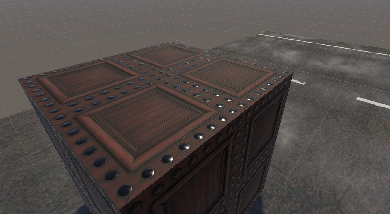
this bit in the textures and materials section doesn't really make sense to me.

do i make the folder in advance on my pc with the extracted files inside and call it _materials and drop that into unity?

do i make the folder *in* unity and drop the files in that?

it sounds like all of the bits in the zip are supposed to create one usable material that can then be applied but i cant figure out how to do that, any help?
YoumyCakes 7/out./2021 às 3:34 
Pictures and stuff would be nice too but this is good. Will help me a lot
marrow 19/set./2021 às 8:55 
░░░░░░█▐▓▓░████▄▄▄█▀▄▓▓▓▌█ Help
░░░░░▄█▌▀▄▓▓▄▄▄▄▀▀▀▄▓▓▓▓▓▌█ Doge
░░░▄█▀▀▄▓█▓▓▓▓▓▓▓▓▓▓▓▓▀░▓▌█ Take
░░█▀▄▓▓▓███▓▓▓███▓▓▓▄░░▄▓▐█▌ Over
░█▌▓▓▓▀▀▓▓▓▓███▓▓▓▓▓▓▓▄▀▓▓▐█ Steam
▐█▐██▐░▄▓▓▓▓▓▀▄░▀▓▓▓▓▓▓▓▓▓▌█▌ Copy
█▌███▓▓▓▓▓▓▓▓▐░░▄▓▓███▓▓▓▄▀▐█ And
█▐█▓▀░░▀▓▓▓▓▓▓▓▓▓██████▓▓▓▓▐█ Paste
▌▓▄▌▀░▀░▐▀█▄▓▓██████████▓▓▓▌█▌
▌▓▓▓▄▄▀▀▓▓▓▀▓▓▓▓▓▓▓▓█▓█▓█▓▓▌█▌DO IT.
█▐▓▓▓▓▓▓▄▄▄▓▓▓▓▓▓█▓█▓█▓█▓▓▓▐NOW!
Spoon 14/set./2021 às 13:39 
@Kezzers speak for yourself, i'd much rather have this open than constantly playing and pausing something
Kezzers 26/ago./2021 às 10:24 
Honestly, this would be better if made into a YouTube Video. Nobody is going to have this Steam Guide open and make a VRChat world with it.