Empyrion - Galactic Survival

Empyrion - Galactic Survival

279 ratings
Signals and Circuits Tutorial
By NimrodX and 1 collaborators
Ever wondered what all that stuff about signals is and what the options mean? This guide will answer ALL of your questions. Signals... How to use them, what they do, what all those configuration options mean and where they are in the UI. Comes with a simple tutorial blueprint that you can easily spawn in creative mode.
5
2
14
3
   
Award
Favorite
Favorited
Unfavorite
What are Signals and those weird "Custom" switches in my Control Panel? What are Circuits?
Signals

To put it simply, signals are wires with names. That's really the best way to think of them. They're digital wires that can have one input and output to multiple devices. These wires can be connected to things by typing their name into the right box in the UI.

Things like sensors and levers (switches) can output 0 (off) or 1 (on) to a signal, and then other devices like lights, doors, shutters, weapons, etc, can receive those signals to control their off/on state. In the simple case of a lever connected to a light, this is little more than a wire between the lever and the light except that the wire has a name. You can then connect the wire to more lights by telling the lights the name of the wire they should be connected to.

Circuits

In the game, a "circuit" is something that isn't a device block but can do things with signals, such as take multiple input signals and produce an output signal according to a function. That might sound complicated but don't worry because the functions are pretty simple. This will tell you all about them.

Think of circuits as virtual blocks that you can plug input and output wires into. If you want to get complicated you can also combine them together, but this tutorial will focus on the basics so you'll know how to use the UI to combine them if you want to experiment with something complicated.

The "Custom" Switches

Those are actually called shortcuts and are kind of lame. They're actually just shortcuts for the "Active" switch in a Control Panel device group so you can have several switches enabling and disabling groups all on the main control panel tab. They can't do much but I'll mention them because they're less trouble than using Signals for simple cases, and because they conflict with using signals. So in general, only use one or the other.
Setup for the Tutorial
First, before you do anything else, subscribe to this HV blueprint:

https://steamcommunity.com/sharedfiles/filedetails/?id=1582278219

No, it's not really a vehicle. It's a demonstraton display for our tutorial here. I will be referring to it constantly.

Start Up Creative Mode

After subscribing and giving steam a minute to download the blueprint, load up the game and start a new Creative Mode scenario type game. I recommend something like this:


Now, hit F2 and find the Signals Tutorial blueprint.


Spawn it above flat ground or trying to use it will suck.


You might need to add some fuel to the fuel tank to keep the generator going. If so, hit 'H' and spawn yourself some fuel, then fuel up.


Ok, so now you should have something like this up and running. Don't forget to power it on with 'Y' (or hit 'P' and turn the power on).


Not fancy but it should be good enough for learning this stuff without any unnecessary distractions.
Naming Conventions
0 = Off = False

1 = On = True

If you learn nothing else here then learn this: When using signals things will get very vey confusing very fast if you don't have a good naming system! For this tutorial, here is the naming system I'm using.

  • The devices are named based on which example they're part of. So LeverE3A is the "A" lever in Example 3, and LightE3C4 is the 4th "C" light in Example 3. In short it's <Devictype><Example Id><Letter Group><optional number in the letter group for letter groups with more than one light>.

  • Signals are named in a similar manner. So the Tx Signal (output) of LeverE3A is named SigE3A. Basically the simple signals from levers and sensors are all named Sig<Example Id><Letter Group>.

  • Signals output from circuits however are named Sig<Example Id>Out. So SigE3Out indicates that it's the output signal from the circuit used in Example 3. I can keep this simple because there's only one curcuit per example, thus only one circuit output per example.

For more complicated projects you may need a different naming system that's more flexable or appropriate for what you're doing, but whatever you do use a consistent naming system so you can tell what a signal is from the name. Otherwise it will be hell to figure out what lever is outputting to a signal named "Joebob" when you have tons of levers around.

Don't worry if this doesn't make sense to you yet. It will make sense shortly. Just keep going.
Example 1: Using the "Custom" Switches
This example doesn't even use signals much less circuits. It's now time to explain what these "Custom" switches are.

Everything in the E1 (Example 1) section is in it's own group.

Notice I have named one of the "Custom" switches E1.


Now, click on Devices and click on the Example 1 device group.


Notice that thing up there that says "Shortcut". It's set to "E1". That means the E1 switch on the main control panel tab will act as a shortcut for that "Active" switch over to the right.

That's all it does. LAME! But it's easy to set this up if all you need is to be able to diable or enable a group of devices. It only works if you're OK with affecting all devices in a group though.

Also note that one shortcut (custom switch) can be assigned as the shortcut for multiple groups. Sometimes that might be easier than moving everything into a single group.

Go back to the main tab and notice what happens when you flip the E1 switch. Notice that the lever does NOT get switched on or off, it gets disabled or enabled.

Remember this because it will be important later! Levers have two types of state: switched on/off, or enabled/disabled. Input to a lever does not switch the on/off state! It disables or enables the lever! This may not be what you were expecting but it's how things currently work with levers.

Note: In case you haven't figured it out already, to put things in a group, create a new group by hitting that + button. Then click the thing you want to move into the new group and hit that icon that looks like a piece of paper. Once you do that, you can move other devices into the same group you moved something into last time by clicking the next device then hitting that icon that looks like overlapping pages. (It's a "do last move again" button.)

Ok, on to more complicated stuff with signals and circuits.
Examples 2-4: Signals and Simple Circuits
Ok, so you see what those "Custom" switches are. They're actually just shortcuts for the Active switches on groups, but they do nothing unless you configure one or more groups to use one of them.

Signals are a bit more detailed though.

First law of signals is: every signal can only have one source device. In other words, if you have a lever that outputs/transmits a signal (specified under "Tx Signal"), you can't have another lever that outputs to the same signal name. So I recommend naming signals based on the name of whatever generates/transmits them.

Example 2: The AND Circuit

Walk over to E2, hit P to open the control panel, click on the Signal Logic tab, then select one of the E2 levers.


Notice that Tx Signal has been set to a name: SigE2A meaning "the signal from Example 2 Lever A". Also notice that the B lever has been set to a similar consistent name.

Now look over to the right under Circuits where it says 2x AND & at the top. 2x AND is a type of curcit that takes two signals as inputs, and outputs a new signal as the output.

The definition of AND: If both inputs are 1 (that is, if A AND B are both 1) then the output is 1. Otherwise the output is zero. So in other words, the output is always 0 except for the one situation where both inputs are 1.

Now click on the lights and notice which signals they use to detrmine their off/on state:

Some lights just take their signal directly from a lever. The signal name is selected in the menu and the type is set to "Follow". This means when the signal output is 1 the light will be on, and when it's 0 the light will be off. Ignore the other options for now, they will be explained.

Most of the time you probably want Follow as the behavior type.

Notice that one light doesn't get it's output from a lever, it get it's output from the AND circuit.

Can you guess what's going to happen here? Flip the switches around to see if you're right.

What should happen is, the A and B lights go on or off with the corresponding lever, but the C light only comes on if BOTH levers are on. That's what AND does.

On a final note, there's also a 4x AND which I don't demo here, but it's the same as 2x and except with four inputs. As before, all inputs must be 1 for the output to be 1. So, if you only need three inputs on an AND then you can force the unused 4x AND input to 1 which will effectively cause it to be ignored.

What if you want a 7x AND? Well, just create two 4x ANDs and feed the output of the first AND into one of the inputs of the second one. Now that one will only output 1 if all 4 of it's inputs are 1, and the second AND will also need its other three inputs to be 1 to output 1. So you can get 7x 16x or whatever you want by chaining multiple ANDs together.

Combining "Custom" switches (shortcuts) with Signals

In short, don't do it. Notice I created a Custom switch in the main control panel called E2 so you could see why this is a bad idea. When you flip it, 1) the levers are just disabled, not switched 2) the lights are forced on or off regardles of what the output of the AND circuit or levers is. So hopefully you can see from this that the custom shortcut switches are a good way to screw up your signals and circuits and get them into a weird state that takes trouble to get out of. They basically override everything which screws up the logic.


Example 3: The OR Circuit

Ok, so walk over to E3 and check out the Signal Logic tab for the Example 3 group. This should be looking pretty familiar except this time we're using the second circuit in the list: 2x OR. This is an OR circuit with two inputs.


The deinition of OR: If either the A OR B input is 1 then the output is 1, otherwise the output is 0. In other words, the output will always be one unless BOTH inputs are 0.

Looking at how the signals are connected in the curcuit, can you guess what's going to happen here?

Flip the levers around and notice that turning either lever on by itself is enough to light up all four of the C lights.

The only reason I put 4 C lights there is to demonstrate that multiple things can receive the same signal even if only one thing can send a signal.

Like with AND, you can chain these together to get as many OR inputs as you want. Create multiple ORs and feed the output of one into another. If any single input is 1 the output will be 1.


What's that XOR?

There's another type of OR available called XOR or Exclusive OR. It's called that because it "excludes" the case where both inputs are 1 and treats that case as false.

Deinition of XOR: If both inputs are the same, the output is 0. The inputs are different then the output is 1.

Think of it as OR with the AND truth condition excluded. Or just forget that and think of it as a circuit that compares two inputs and outputs 1 if they're different.

Feel free to try adding a 2x XOR curcuit real quick then switch the Example 3 signals around to replace the OR with an XOR to get a feel for how it works, and how to manipulate this stuff in the UI.

Unlike AND and OR, you can't really just get more inputs (mathematicaly speaking anyway) by chaining them. You can chain them together but the boolean math gets more complicated at this point. This can be useful but it may not work the way you expect so you'll have to experiment. (Generally this will cause the output to change any time any of the inputs are changed.)


Example 4: The Inverter Curcuit (NOT)

The inverter is also called NOT and is even easier than the previous ones. The output is the opposite of the input: if the input is 1 then the output is 0. If the input is 0 then the output is 1.


Play with that a bit and notice that this could be really useful for switching the color of light in a room from white to low intensity red for example, like on a submarine in the movies.

Ok, so now that you know what the Inverter also known as "NOT" circuit is, you may have noticed that there are some funky versions of AND, OR, and XOR called NAND, NOR, and XNOR. Guess what? Those are exactly the same as the regular versions except the output has a built-in inverter stuck on it! So while AND normally outputs 1 only when both inputs are 1, NAND will normally output 1 and only output 0 if both inputs are 1. Same logic for the others. They're exactly the same as whatever except with the output flipped to it's opposite (1 to 0 or 0 to 1).

All those do is save you from having to create an inverter separately. Otherwise they're exactly the same as if you used the regular gate type and output through an inverter.

There's another easier way to invert stuff that I'll mention in a bit.

In case you didn't already know, all these circuits are real things used to build your CPU. Theoretically you could build a CPU with the curcuits in the game, but it would be a real pain in the ass so I wouldn't recommend it! Spend your time learning Verilog instead.

As for chaining AND, OR, XOR, and inverters together, when you do that you create something sort of like a combination lock called a truth table where the output will be 1 ("true") only for certain combinations of 0/1 inputs. Usually you don't need to get this complicated but it can be done if necessary. Your CPU uses clever arrangements like this for specific purposes like decoding instructons and addig numbers together, but the usefulness in the game is kind of limited at this point.
Example 5: The SR (Set/Reset) Latch
Example 5 looks like this.


There are laser tripwires A and B, and some lights marked C.

Before tripping the tripwires, lets talk about how these are connected and then see if you can guess what will happen before testing it out.

Example 5 uses something called an SR Latch, or Set/Reset Latch. These are actually the basis of the ram in your computer which has zillions of them, but we only need one fortunately. An SR latch is basically one bit of memory. It will remember whether it is "set" (to 1) ro "reset" (to 0).


The way the tripwires behave this is: the normally output 0 when nothing has tripped them. Then when they detect something they output a 1, then go back to 0 again. So they output a signal that looks something like 0000000 <trip the tripwire>1..00000000. So they're like momentary pushbuttons.

The A tripwire outputs it's signal to the SET pin of the SR Latch, and tbe B tripwire outputs it's signal to the RESET pin of the latch.

The SR Latch will set it's internal bit of memory to 1 as soon as it sees a 1 on it's SET pin, even if the 1 only lasts a moment. Even after the 1 goes away, it will keep outputting 1. That's why it functions as memory.

When it sees a 1 on the RESET pin, even a brief pulse, it will change it's state to 0 and keep outputting 0 forever or until it sees a brief 1 on the SET pin again.

Notice both C lights are follwoing the output of the latch so they're exactly the same. I could have just used one light, but I said ♥♥♥♥ it, we're puttin two lights on this ♥♥♥♥♥!

Now you've probably figured out what's going to happen when the tripwires are tripped so go ahead and give it a shot.

Anyway, you can see that the SR Latch is basically your "soft switch". And yea you could implement a GB of RAM in the game with a bunch of these but I wouldn't recommend it! One bit ought to be good enough for anyone.
Example 6: Levers Receiving Signals
The point of this example is mostly just so you can see how it (doen't) works.

The A lever outputs its signal to the B lever. Notice that the B lever is disabled until the A lever is switched on.


The B lever both "follows" a signal and emits a signal.


Play with it and take heed! This does not synchronize the levers! It causes one lever to enable/disable the other lever!

Maybe that could be useful as a failsafe or something I don't know. I wouldn't be surprised if the devs change this behavior or add more options or something so this isn't necessarily going to be true in the future.

But this is how it works now so be aware.
Examples 7-8: Signal Handling Types and Control Panel "Signal" Switches
Example 7: Follow, Toggle, and the Mysterious "I"

This time we're not using levers, we're going to use the "Signal" switches in the main tab of the control panel.


These actually work just like levers outputting a named signal but they're in the control panel instead of mounted on a block. So you may find these to be more helpful than levers which can take up too much space on small vehicles etc.

But the real point of this is to show you the signal handling options and what they do.

  • Follow - This is what we've been using so far and is the basic case. The on/off or enabled/disabled state of the device follows the signal, so if the signal is 1 then it's on, and if it's 0 then its off. Most of the time you use this.
  • Toggle - This causes the device to toggle it's state from on to off or vice versa whenver a 1 pulses briefly on the input. (This resembles the behavior of a T or "toggle" flip flop which doesn't exist as a circuit in the game.) If you had a pushbutton generating a signal then you'd want to use this for "push on, push off" type behavior.
  • On - Device turns on when it receives a 1 and stays on forever. If it's already on then nothing happens. This is similar to the SR Latch with only the SET pin connected.
  • Off - Device turns off when it receives a 0 and stays off forever. If it's already off then nothing happens and the signal can never turn it back on.


The signal response types are set up as follows. E7A is set to follow which behaves as you'd expect. Try switching the SigE7A switch on the main control panel and notice it behaves normally.

E7B is set up as Toggle. Play with the corresponding switch in the control panel and notice what happens.

E7C is also set up as Folow, but notice that little checkbox marked "I" has been checked.

Have you been wondering what that was for? Well wonder no more. That causes the response to the signal to be inverted as in I for Invert (clever). Play with the switch and notice that when it's off the light will be on, and when the switch is on the light will be off.

You can easily invert anything using this checkbox which make this simple case less trouble.

That's all there is to it. So now you know what these options are!

Example 8: The Off and On Response Settings


The off and on settings seem kind of useless but here's an example you can play with to understand the behavior. Notice if you use the signal to force the device to on or off, you can only flip it back using the Activate switch.
Some (Optional) Theory
Did you know there's a "universal logic gate" that can be used to construct all other logic gates? It's the NAND gate. Using only that, you can construct the others. The computer (which by today's standards seems more like a large elaborate pocket calculator) used to land on the moon was constructed of nothing but NAND gates. Fortunately you don't have to bother with this, but I just mention it so you'll know there are a bunch of mathematical properties of these things.

Here's some more advanced stuff about logic gates if you want to check it out:

Logic Gates Tutorial[www.instructables.com] with a somewhat practical example.

Logic Gates (formal definitions)[www.tutorialspoint.com]
Combinational Circuits[www.tutorialspoint.com]
Boolean Algebra[www.tutorialspoint.com]
Sequential Circuits[www.tutorialspoint.com] (Note: Trying to construct your own flip flops doesn't work in this game because the timing of the simulation isn't realistic enough.)

You can find others by searching for "logic design".

Another interesting thing, if you want to learn how to build a computer from scratch, here's a free gamified tutorial that teaches all the basics starting from only NAND gates:

http://nandgame.com/

And here's a newer rather awesome commercial game that's sort of like nandgame on steroids with a "story mode" to it, plus a sandbox:

https://store.steampowered.com/app/1444480/Turing_Complete/

For those looking for something even more hardcore:

https://store.steampowered.com/app/1885690/Virtual_Circuit_Board/
https://store.steampowered.com/app/576030/MHRD/
Your Turn
Ok, so now you know just about everything except maybe how to combine circuits in complex ways which I will not cover here. But you know enough that if you think of something you should be able to try it.

The only circuit type I didn't mention or demonstrate is the Delay, but it's pretty obvious what that does. Maybe that's a good one to try out here. It just delays the change on it's input to it's output.

So do whatever and give this a shot setting something up from scratch:


Summary of Signals/Circuits Setup

  1. Add switches and lights (or whatever inputs and outputs you have).
  2. Click the Devices tab. Assign devices to one or more groups. (They don't need to be in the same group, I just combined related things in the same group for these example.)
  3. Use a sane naming convention!!!
  4. Name the devices. Did I mention to be sane about it?
  5. Click the Signal Logic tab
  6. Name output signals for output devices (like levers). Remember, each signal has only ONE device that generates it so it's safe to name the signal after the device that generates it.
  7. Add a circuit, or more than one.
  8. Select signal inputs for circuit.
  9. Type an output signal name for the circuit.
  10. Select signal inputs for devices you want to control. Remember you usually want to use follow and some devices like shutters used as ramps may need "I" checked.
  11. Test it out.

Suggested Mini-Project

Try creating a light that is automatically activated by a motion sensor that turns off after 10 seconds. The motion sensor is under the Signal and Sensor block that looks like a lever.

Hint: Use an SR Latch and a Delay. Connect the sensor to the S pin of the latch and the input of the Delay, then connect the output of the Delay to the R pin of the latch. Set the output signal of the latch to control one or more lights.

This is similar to those power-saving freezers at the grocery store that turn their lights off until someone walks near them, then shut them off after nobody is dected for a while.
Conclusion
Ok, that took a while. I'm done!

Now I'm ready to take this mofo for a RIDE.


HELL YEA WHEEEEEEEEEEEEEEEEEE WOOHOO
Quick Reference
Grouping Devices

Open control panel with P. Click the Devices tab, create a new group by hitting the + button.

Click the thing you want to move into the new group and hit that icon that looks like a piece of paper.

Once you do that, you can move other devices into the same group you moved something into last time by clicking the next device then hitting that icon that looks like overlapping pages. (It's a "do last move again" button.)

"Custom" Control Panel Switches

Open control panel with P. Name a Custom switch.

Click Devices tab.

Click a Device Group Name.

Select the name of the custom switch from the Shortcut menu in the top center.

Set a Tx Signal

Click Signal Logic in the control panel.

Click a device capable of output.

Type a signal name in the text box labeled Tx Signal under CONFIGURE SIGNAL.

Receive a Signal

Click Signal Logic in the control panel.

Click a device capable of doing something with input.

Set On/Off to the previously named signal under CONFIGURE SIGNAL.

Set the menu next to it to:

  • Follow - The normal case. The on/off or enabled/disabled state of the device follows the signal, so if the signal is 1 then it's on, and if it's 0 then its off. Most of the time you use this.
  • Toggle - This causes the device to toggle it's state from on to off or vice versa whenver a 1 pulses briefly on the input. (This resembles the behavior of a D flip flop which doesn't exist as a circuit in the game.) If you had a pushbutton generating a signal then you'd want to use this for "push on, push off" type behavior.
  • On - Device turns on when it receives a 1 and stays on forever. If it's already on then nothing happens. This is similar to the SR Latch with only the SET pin connected.
  • Off - Device turns off when it receives a 0 and stays off forever. If it's already off then nothing happens and the signal can never turn it back on.

The checkbox labeled "I" Inverts the signal before using it. So an off signal will turn something on etc.

Adding A Circuit

Select a circuit from the list and click Add Circuit. Configure the input signals and name the output signal.

  • AND - Output is 1 only if ALL inputs are 1.
  • OR - Output is 1 if ANY inputs are 1.
  • XOR - Output is 1 if inputs are different, 0 if all inputs are the same.
  • Inverter - 0->1 and 1->0 (output opposite of input)
  • NAND, NOR, XNOR - same but with a "built in" Inverter on the output.
  • SR Latch - Outputs 1 when SET and 0 when RESET. SET and RESET are triggered when the input receives a 1 pulse ("brief on").
  • Delay - what it sounds like.

Set unused inputs of 4x AND to 1.

Set unused inputs of 4x OR to 0.

Advanced Reference on Logic Gates

Logic Gates (formal definitions)[www.tutorialspoint.com]
Combinational Circuits[www.tutorialspoint.com]
Boolean Algebra[www.tutorialspoint.com]
Sequential Circuits[www.tutorialspoint.com] (Note: Trying to construct your own flip flops doesn't work in this game because the timing of the simulation isn't realistic enough.)
Practical Examples
This final section gives some practical examples of how to use these in real designs.

Use XOR to control something with multiple switches

Here's one (from jcewazhere) where XOR is used to allow a hangar door to be opened using multiple levers. This is sort of like the way switches are wired in a room in your house so that flipping any switch turns the lights on or off.

https://steamcommunity.com/sharedfiles/filedetails/?id=1582764106
https://steamcommunity.com/sharedfiles/filedetails/?id=1582764094

This is a bit of a hack because ideally there would be a way to keep multiple switches in sync, or there would be pushbuttons that all trigger things set to Toggle through an OR gate, but since we don't have pushbuttons or a way to keep switches in sync with each other, this is a good way to do things for now.

A more elaborate example: power use modes on a CV

This is the Chickenhawk.


The Chickenhawk is a power-hungry CV with too many engines. It really doesn't need all those engines for routine stuff like landing, flying around, and achieving orbit.

It also has lots of extras like a constructor and other workbench type stuff that should be powered off much of the time, especially when sitting on a planet where it really only needs its guns to work.

So, to solve the second problem I have created a Powersave signal that, when enabled, will shut off lots of things including all of the engines, the constructor, and anything else that doesn't need to operate at the moment.


So I land on a planet and just enable Powersave. The engines and everything that's not needed shuts off and the guns stay on (as long as the Cannons switch is on anyway). The Fridge also keeps running. But it saves lots of power by shutting almost everything off.

So I set up everything that needs to power down in powersave mode to Follow Powersave with the I (Invert) checked because when powersave is ON we want those things to be OFF.


But what about when I do want to fly around, yet still want to save some power? Well it has about twice as many thrusters as it needs for cruising around or even making orbit.


It really only needs 12 m/s^2 to take off under normal 1G gravity or so, and minimal thrust in all directions other than down and rear.

So I want the following to happen:

  • When in powersave mode, all thrusters are disabled becaue I'm just parked and want to save maximum energy.
  • Normally, when not in powersave mode and I'm flying around, I want half the thrusters disabled.
  • Sometimes I want ALL of the thrusters enabled so I can try to dodge fire or run away from stuff. I also need them if the ship flips over or if a planet has significantly more than 1G of gravity.

But normally trying to control the engines wtih the Powersave signal would make it impossible to control any engines with any other signal.

So I create an Inverter to get myself a PowersaveOff signal that is 1 (ON) when Powersave is OFF.

Then I create a FullPower signal and intput that signal and the PowersaveOff signal into an AND gate to get a FullThrust signal. This signal will only be 1 when a) powersave is OFF and b) FullPower is ON.


I set half of the engines on each side to Follow the FullThrust signal so they only come on when I need full thrust AND when Powersave is OFF.

Now when Powersave is off and FullPower is also off, my thrust is this:


Which is good enough for most of the time and it uses something like 3.88MW inste ad of 7.56MW, saving me much fuel and fuel mining time.

Now, I could have done this differently by reversing the logic of the FullPower signal switch and calling it LowPower meaning "use low power when this is enabled". If I had done that, then I'd want to use a NOR gate which would give me:

  • Powersave 1 NOR LowPower 1 = 0 (extra thrusters always off in Powersave ON)
  • Powersave 1 NOR LowPower 0 = 0 (same as above, basically don't care about LowPower when Powersave is on because all thrusters should be off, lowpower or not)
  • Powersave 0 NOR LowPower 1 = (Powersave is off but we still want extra thrusters off because LowPower is ON)
  • Powersave 0 NOR LowPower 0 = 1 (the only case were the extra thrusters should be on, not in powersave and not using LowPower)

Reminder: NOR is just OR with an inverter after it. So if either or both inputs is 1, the result is 1 when is then inverted to 0 and output. Only when both inputs are 0 is the result 0 and then inverted to output 1.

This also gives me the desired behavior, though with different logic for the control switch ("use low engine power when on" vs "use max engine power when on"). I just picked FullPower because I wanted "on" to be more the exception than the rule.

Here is the Chickenhawk if you want to look at the configuration. (Just spawn in Creative Mode.)

https://steamcommunity.com/sharedfiles/filedetails/?id=1589387233
51 Comments
IzDreamSKLTH Jun 24, 2023 @ 5:40pm 
i need help
i want to make some device loop working
working on 300 secound
and then stop 600 secound
how i can make circuit
felixcelsus May 29, 2023 @ 12:36am 
So I'm trying to do what MAD asked, with the hanger door. I've got two motion sensors, one inside and one outside. The devices have unique names (SenHI for Sensor Hanger Inside, and SenHO for Sensor Hanger Outside).

SenHI has Tx Signal named SigHI.

SenHO has Tx Signal named SigHO.

They're on the floor, aimed upward to catch anything passing over them, set to read 5 blocks high. The hanger door is the only one on this structure, and just named HD.

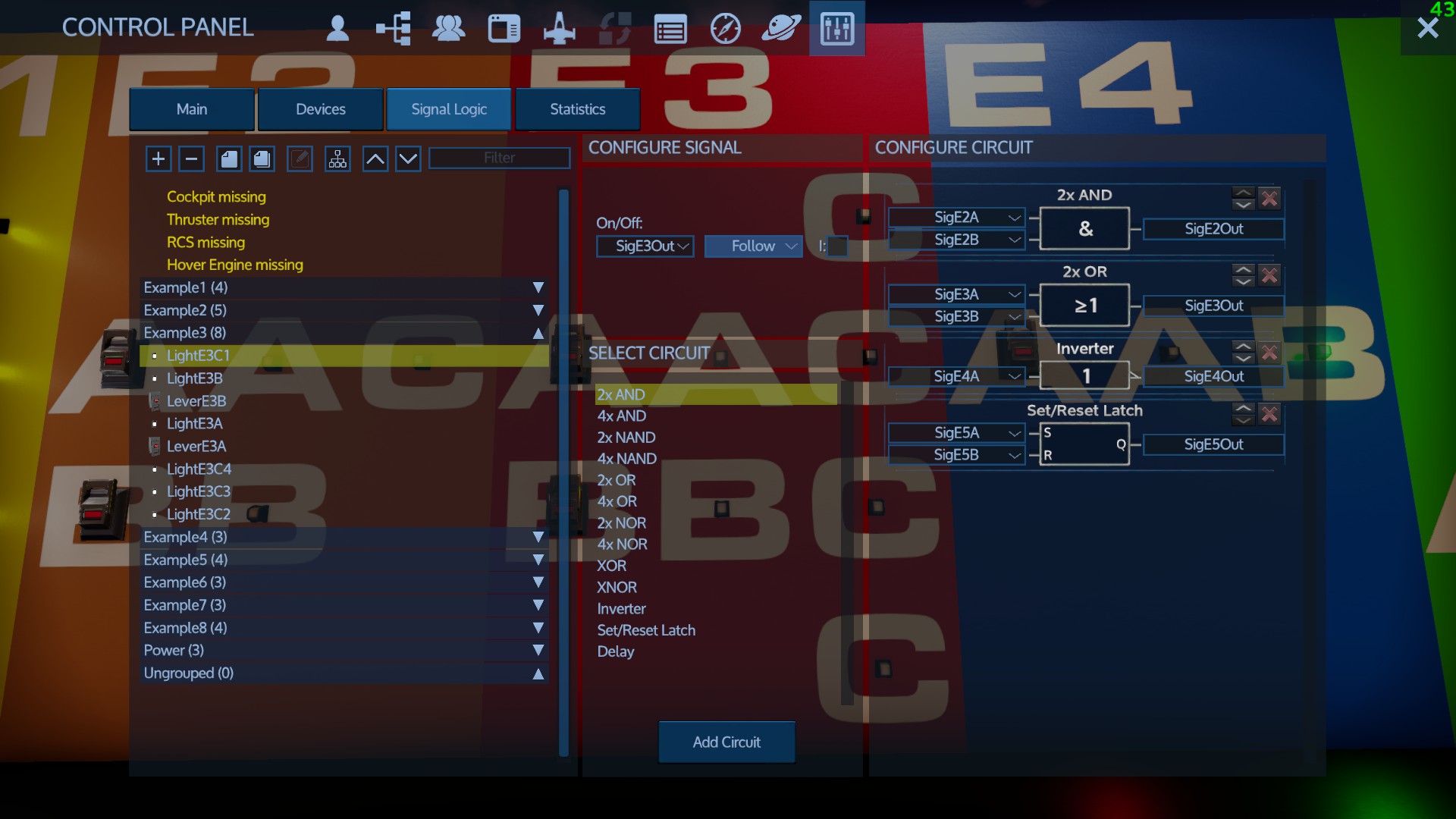
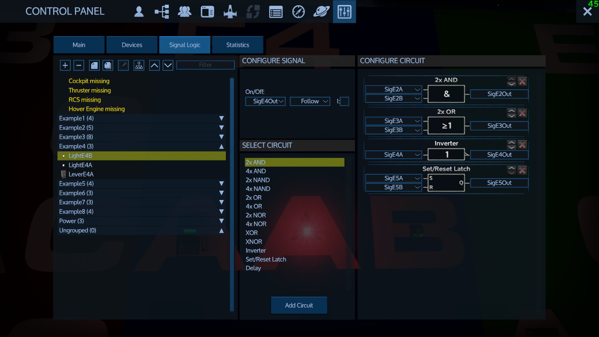
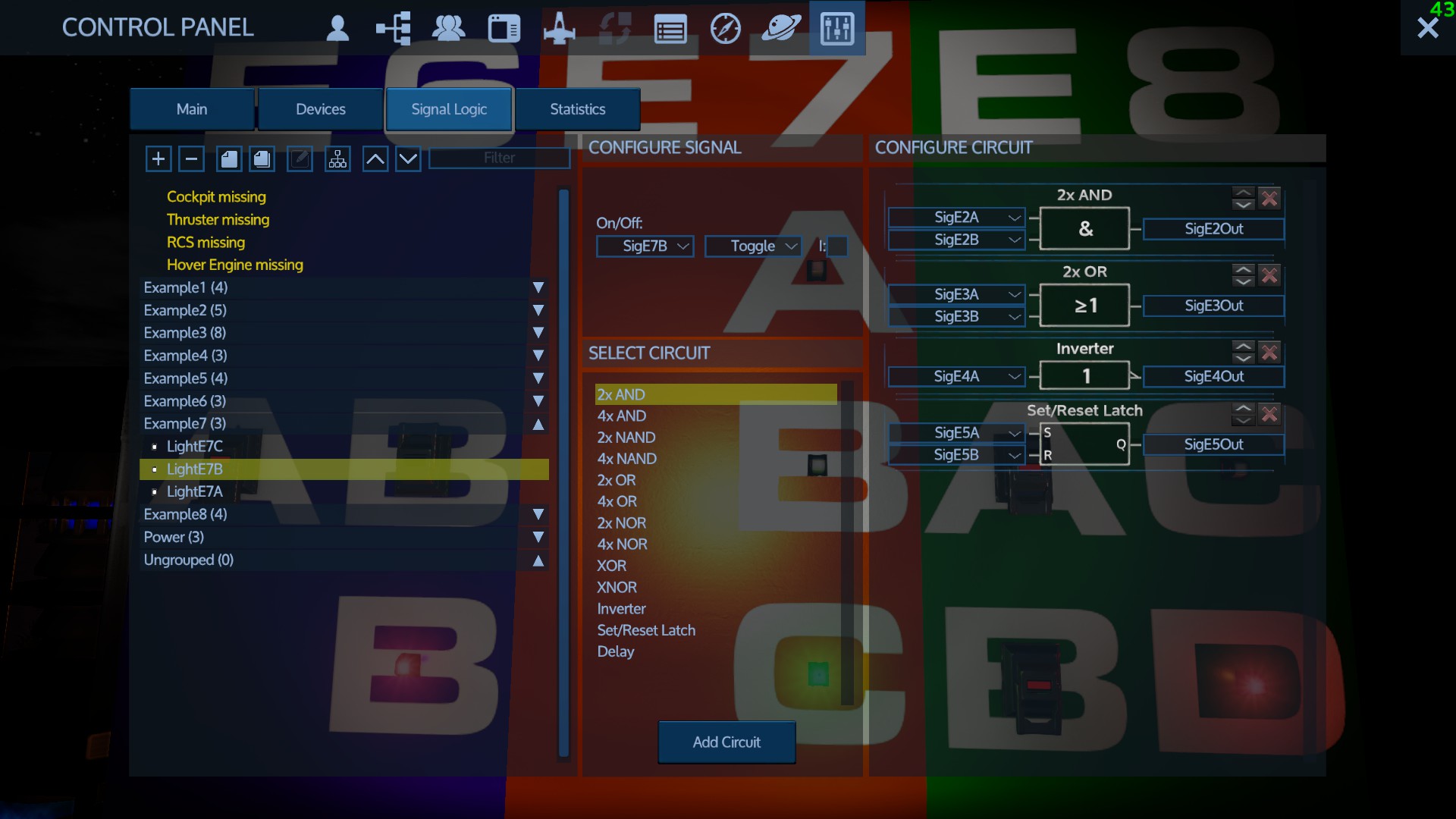
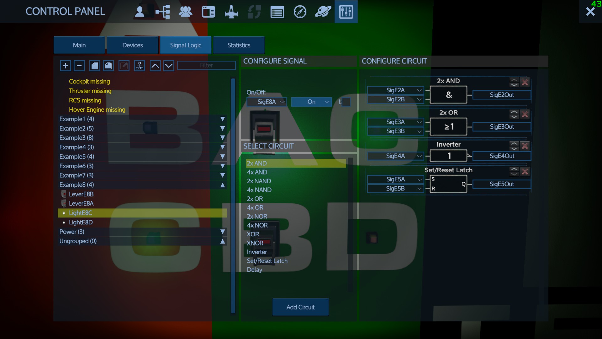
I made a Set/Reset latch circuit. S is SigHI, R is SigHO, and Q is SigHD. The door (HD) has SigHD set to Follow (I've tried follow and toggle both.)

And no matter how much I run over, fly over, or jump up and down on those sensors, my hanger door just won't move unless I go do it myself as the good devs intended.

I'm sure the answer to this is something incredibly simple that I've missed, but any help would be enormously appreciated!
NimrodX  [author] Dec 6, 2022 @ 8:30pm 
That can be done with motion detectors
MAD Dec 5, 2022 @ 10:58pm 
Can you do a hanger door that opens when you fly near it and closed once your inside?
Working both ways.
:Authorized-Representative: Oct 7, 2022 @ 5:58am 
stopped reading at example 1
Christ Catnap Feb 11, 2022 @ 9:23pm 
I am grateful for your 'hands on' in-game tutorial NimrodX, will go through it a.s.a.p.. I learned plenty just reading your post about the Empirion Electrical Code (EEC) has put me back in the drivers seat

Nonetheless japp_02 brought up a good point about corruptions over time, and MoronWMachinegun totally opened the inspiration portal for me as to buying time system wide.

This is as close to Process Technology I will allow myself to get again.

All the Best!
japp_02 Feb 6, 2022 @ 3:41pm 
Great tutorial. Once you understand the logic of signals with the help of this tutorial, there is however the other part which you need to also understand: how does the game perform exactly with it. Do levers/sensors need to be active before coding a circuit? You may have to use the Invert option (I checkbox) to make your circuit work, that's not logic but it's how the game works. And there is the case where the best circuits will stop working at some point if you play longer, doors don't open anymore or stay opened and such, a complete shut-down / reloading of the game will help.
With the 2x OR circuit, I notice that you may not have the output name be a On/Off trigger for either the 2 compounds of the circuit, or the circuit will not work, this particularity is worth to add maybe because difficult to figure out.
ItSammy! Jun 27, 2021 @ 12:58am 
I just want to make a damn motion sensor that opens a door. I wasn't expecting something that sound like coding language from my IT classes and now the PTSD is kicking in.
MoronWMachinegun Mar 12, 2021 @ 7:35am 
Great job. I used a delay and XOR to do a timed enable for my teleporter in the tutorial. That way it only stays on for 20s when activated, and doesn't drain my base power while I am away. :D
Joel of Pytt Feb 21, 2021 @ 6:05pm 
Thank you for the tutorial. Do you know what the "Lock/Unlock" configuration is useful for? I've been experimenting with it and cannot figure out what effect it has. A little about that would be a nice addition to the tutorial.