Oxygen Not Included

Oxygen Not Included

1,637 ratings
Useful Construction Patterns
By Jahws
A collection of useful structures for in-game colonies, currently up-to-date for ONI's official release. Note that additional late-game oriented patterns may be found in my late-game guide; I've yet to convert those over for use here.

Each build includes exposition regarding the room's role, advantages, and design philosophy.
11
4
33
2
3
5
3
   
Award
Favorite
Favorited
Unfavorite
Intro
This guide contains a number useful construction patterns and structures that can be reasonably constructed in a live survival (non-sandboxed) game. As such, these may see frequent use and reference from my other guides. Each build will include images of each relevant overlay and will include exposition on the room's design, advantages, disadvantages, and requirements. In time, I plan to add small, edited videos demonstrating how each one operates and/or critical parts of the setup.

For simple, basic early-game rooms intended for the first twenty cycles or so, check my early-game guide below instead.

https://steamcommunity.com/sharedfiles/filedetails/?id=1359110726

This guide does contain info for some of its later, more complicated builds, such as the multi-stage Coal Generation room.
Washroom Sieve Loop
Goal
This room is designed to facilitate non-potable Water reclamation, conserving a base's clean (germ-free) Water supplies. While not strictly necessary on Terra, this should prove extremely useful for Forest biome starts (like on Verdante and Arboria-type maps).

Approximate Timing
This is an early-game build pattern designed as an extension of a base's first plumbing-based bathroom, once the colony can afford the additional research and construction time investments.


Design Basics
By utilizing a Water Sieve, a Lavatory room's non-potable Polluted Water output may be purified, though not decontaminated. This process tends to expose Dupes to germs, so a Sink is included in a location sufficient to prevent the spread of Food Poisoning. A small dump station for Polluted Water is included, allowing external sources of contaminated Polluted Water to be handled as well.

If constructed at the same time as the Washroom itself, the only needed input would be an initial bottle of Polluted Water left over from an early Wash Basin. The only Power this build pattern should draw is from the Water Sieve whenever there is new Polluted Water to be cleaned and the clean Water tank is not yet full.

Researches Required
  • Sanitation (Tier 2) - unlocks the Sink (and Lavatory)
  • Distillation (Tier 3) - unlocks the Water Sieve
  • Improved Plumbing (Tier 3) - unlocks the Liquid Reservoir
Design Details

As the Washroom (particularly, the Lavatory building) outputs more Polluted Water than it takes in, it is possible to supply Lavatories with pre-contaminated Water, rather than drawing from the base's remaining pure Water supply. This system utilizes this fact, sending Water in a loop - from Lavatory output to the Polluted Water tanks. By relying on Liquid Reservoirs, we avoid unnecessarily spending extra Power to repump any Water we are given - these structures will automatically forward their contents whenever possible.


Note the use of a Sink in this design pattern. Any Dupe that handles the Sieve's output - contaminated Polluted Dirt - will gain surface Food Poisoning germs. This also applies to any Farmer Duplicants that run Composting errands - and they handle food. Making sure that our Farmers exit through the Sink will help ensure that they don't contaminate the food supply as a result. (Use the same techniques as you would for a Washroom.)

By also including a Bottle Emptier, external sources of bottled, contaminated Polluted Water may be safely dumped in the appropriate tank. If a Dupe ever "makes a mess," this room will be a safe place to dump the germy bottles.

Note that eventually, all of the Liquid Reservoirs will fill, at which point the overflow must be handled in some manner. If this is built at the game's start, that may take over 80 cycles, so this build buys plenty of time for a solution. The easiest solution, of course, is to use any excess for Thimble Reed farming once you have access to the seeds.

If you're playing on a Terra map, you're probably fine simply dumping the overflow into a few Thimble Reeds or other plants that will use up the excess. On maps with less free Water, you might prefer sanitizing it with a setup involving a Chlorine room instead. Apologies that I don't have one ready yet in this guide.
Coal Generator Room (stage 1)
Goal
This room is designed to be the first stage of a coal generation plant, extendable as the game proceeds and power needs grow.

Approximate Timing
This is an early-game build pattern designed to act as a base's first stable power source. Additional stages (which are separate components of this guide) are added later to enhance the room's capabilities and benefits through the mid-game.


Design Basics
Coal Generators are often the first available form of automatic Power generation available for a colony. Since there's a natural tendency to start building them early in a game, this build pattern is designed as the first stage of a modular, extensible power plant room that we can continue to implement as we unlock more buildings and gain access to more skills. While a few advanced technologies are required here, it's the minimal amount required to ensure the most efficient operation of the Coal Generator possible.

Researches Required
  • Brute-Force Refinement (Tier 2) - unlocks ability to refine Metal, which is needed for the Automation structures involved.
  • Sound Amplifiers (Tier 3) - unlocks the Smart Battery
  • Advanced Power Regulation (Tier 3) - unlocks Heavi-Watt Wire and the Small Power Transformer
  • Smart Home - needed to unlock Automation
Additional Recommendations
  • Pressure Management (Tier 2) - allows use of Airflow Tiles (will be required in Stage 2)
Design Details


While not strictly necessary with a single Coal Generator, this room uses a main Heavi-Watt Wire line to facilitate larger-scale operations down the line. (This connects the Smart Battery to the Coal Generator and to the Small Power Transformer below.) The Storage Compactor contained within the top room is also strategically located for alignment with higher-tech buildings to be added to the room in its future in the third stage.

While the bottom section may not appear strictly necessary at present, it will be fleshed out thoroughly in this build pattern's second stage. The eventual goal is for this area to serve as the early-game Carbon Skimmer room once the appropriate techs are unlocked - that's Stage 2.

This pattern also serves as possibly the simplest and most elegant way to learn about Automation's usefulness - when the Smart Battery is full, it will automatically disable the Coal Generator in order to prevent wasting Coal unnecessarily. When it empties of power, it will then reactivate the Generator. Waste not, want not!
Coal Generator Room (stage 2)
Goal
This room is designed to be the second stage of a coal generation plant, extendable as the game proceeds and power needs grow. This stage adds the ability to safely handle and process the Coal Generator's main byproduct - Carbon Dioxide - ensuring that it does not overtake the base.

Approximate Timing
This is an early-game build pattern designed to act as a base's first Carbon Skimming system, removing it from the atmosphere to provide more space for that precious, precious Oxygen. Doing so also allows more liberal use of Coal-based Power generation.

As such, this is best built once the techs are first unlocked and once the base is starting to rely upon significant amounts of steady Power. I usually try to implement this immediately after completing construction of the first stage.


Design Basics
By placing a Carbon Skimmer room below the Coal Generators, which themselves should be below the main base, most of the base's Carbon Dioxide output can be automatically funneled to this room and processed without additional requiring additional Power draw from Gas Pumps.
Secondly, connecting the Carbon Skimmer to automated controls allows us to ensure that the Carbon Skimmer is used as efficiently as possible.

Researches Required
Stage 2 of this room assumes that stage 1 has been fully implemented and its techs researched. Only techs newly required by stage 2 will be listed in this section.
  • Decontamination (Tier 3) - unlocks the Carbon Skimmer
  • Advanced Automation (Tier 4) - unlocks logic gates - in particular, the AND Gate and FILTER Gates used here
  • Improved Ventilation (Tier 3) - unlocks the Atmo Sensor
Design Details

The main issue with constructing the second stage of the room is its construction requirements, rather than its techs. While the above list of technologies may not seem like much, a significant amount of infrastructure is required to support the second stage. In particular, liquid plumbing is an absolute must for Carbon Skimmer use.


This means that a reliable source of Water must be secured and pumped to the room, while also delivering the output Polluted Water waste safely to a separate location for storage and later processing. Note that it is ideal to output this waste into a designated, uncontaminated tank of Polluted Water, although on maps where Water is plentiful (like Terra) there should be no issue dumping it into the same destination as the output from your Washrooms. The choice is yours.


This pattern also seeks to optimize the Power usage of the Carbon Skimmer via automation. Relevant settings:
  • Gaseous Element Sensor - set to Carbon Dioxide
  • FILTER Gate - set to a minimum of 5 seconds. This ensures that the Skimmer's local atmosphere is consistently Carbon Dioxide. I usually run with 15, but that's me.
  • Atmo Sensor - set to at least > 750 g. This ensures that the Skimmer's local air pressure will maximize use of the Skimmer, which can process up to 300 g/s of Carbon Dioxide. (Once switched off, there is a minor delay before the building actually stops.)

By requiring both a stable Carbon Dioxide and high atmospheric pressure in the Carbon Skimmer room, we ensure that it is never activated when only trace amounts of Carbon Dioxide are present. By default, the building deactivates only when none is present, which can be very wasteful.

For those interested, here's the Power grid for the completed Stage 2:


Once completed, a second Coal Generator may safely be added to the room on the left-hand side when connected by additional Automation Wire, as the Carbon Skimmer will more than able to handle it effectively. I've already added the Heavi-Watt Wire in the image above.

Further down the road, once you've secured a decent source of coolant, adding two more generators to the top will mostly complete the room and provide a great source of initial Power for your first Metal Refinery.
Simple Drecko Ranch
Goal
This room is designed to facilitate early-game Drecko ranching with the mixed-gas atmosphere necessary for Reed Fiber and Plastic prodution.

Approximate Timing
This room is designed for construction around the time a player first enters the Caustic biome, as both the Chlorine and Hydrogen in said biome's gas pockets will need handling. Chlorine should be placed into Gas Reservoir or a low-lying room for storage, while Hydrogen can be added to this room until the upper portions of it are filled as needed.


Design Basics

Dreckos do not eat Dupe food - instead, they eat directly from the plants used to grow produce. Thus, in order to successfully raise them in a ranch, it is necessary to build an in-ranch farm. At the same time, the real reason to do Drecko ranching is to shear them for their valuable goods; this requires a partial Hydrogen atmosphere.

Finally, while Reed Fiber can easily enough be produced through naturally-occurring Thimble Reeds, Plastic can only otherwise be produced through the late-game Oil production cycle. That cycle produces lots of nasty Heat and other issues... but it's only truly necessary when needing large amounts of Plastic. For small, early-game Plastic, Glossy Dreckos are the best bet... but to obtain them, we need a regular Drecko to lay the Glossy morph's egg. For that, they must eat Mealwood.

Accordingly, this room is designed to fulfill all these goals:
  • sustain a Drecko / Glossy Drecko population
  • facilitate Drecko shearing
  • breed Glossy Dreckos

Note that the ranch displayed above can support 3 Glossy Dreckos, 2 Glossy + 2 regular Dreckos, or 5 regular Dreckos at full metabolism.

Once all desired Glossy Dreckos have been bred and the late-game is reached, the room is pre-designed to swap to Bristle Blossom use over Mealwood if desired.

Researches Required
  • Ranching (Tier 3) - unlocks ranching stuff
  • Ventilation (Tier 1) - for the Gas Vent and Gas Pipe (necessary for supplying Hydrogen)
Additional Suggestions
  • Agriculture (Tier 3) - unlocks the Hydroponic Farm tile, for eventual Bristle Blossoms
  • Interior Decor (Tier 1) - for the Ceiling Light
  • Power Regulation (Tier 1) - for the Switch, to deactivate the Ceiling Light when not using Bristle Blossoms as food
The swap to Bristle Blossoms occurs so late that I would personally recommend skipping these "suggestions," though I thought I would include them for those interested.

Design Details / the Drecko math

Dreckos are different from most other ONI creatures in that they directly eat from a growing plant, not its produce. From my observation, 1000 kcal (half a day's worth of Drecko feed) can be supplied by the following:
  • 34% progress from Mealwood
  • 13% (maybe 12.5%?) progress from Pincha Pepperplants
  • 8% (probably 8.3%?) progress from a Balm Lily
These values change a bit for Glossy Dreckos:
  • 51% progress from Mealwood
  • 26% progress from Bristle Blossoms
Extrapolating from that data, there's a pretty easy rule of thumb to note: a regular Drecko will need two domestically-raised plants of your choice per day as food. Each of its two meals reverts any plant's progress by 1 day's worth of domestic growth progress for the plant eaten. For Glossy Dreckos, add one extra plant, as it needs 50% extra per meal - 1.5 days' progress each.

As such, this room is designed for growing plants necessary to obtain Glossy Drecko eggs in order to prusue early Plastic production without worry of Heat or Oil. In the form above, it can sustain 5 regular Dreckos or 3 Glossy Dreckos without issue.

Other Notes
This is definitely not the highest-productivity solution for getting Plastic from Dreckos, but that's okay. This is meant to be a simple, "good enough" build that produces enough Plastic for a base's actual needs... not to mention being simple enough to understand and build at first glance. An industrial solution involving Polymer Presses is advised if you want Plastic to be a commodity rather than a precious resource.
Coal Generator Room (Stage 3)
Goal
This room is designed as the final, high-tech upgrade of a coal generation plant. This stage adds Coal auto-delivery from the central Coal-filled Storage Bin, the ability to apply +50% buffs to the Coal Generators, and the ability to connect the whole room's output to a central Power grid as part of a comprehensive Power system.

Approximate Timing
Later in the game, you'll eventually unlock the Electrical Engineering and Mechatronics Engineering skills, as well as numerous other advanced techs not available at the time of Stage 2. If desired, we can upgrade our Coal Generator room one last time to maximize its potential.


Design Basics
By relocating the Smart Battery to the lower floor, we can make space to install a Power Control Station - an advanced building allowing Electrical Engineering Dupes to apply buffs to our Coal Generators. This is because we've established a Power Plant room:


We've also swapped out the original Power Transformer for its larger variant, the Large Power Transformer. This version can handle 4000 W throughput, able to link the full capacity of the room to a larger Power grid. It can take an automation signal too, allowing the savvy player to selectively operate it based on whatever condition might be desired.

Required Researches
  • Low-Resistance Conductors (Tier 4)
  • Smart Storage (Tier 4)

Other Overlays

Chlorine-based Water Purification
Goal
This chamber is designed to handle overflow from the Washroom Sieve Loop, sanitizing it for safe use elsewhere in the colony.

Approximate Timing
My recommended timing for this pattern depends greatly on your world type, mostly due to the ease of access to large amounts of Water or lack thereof.

For Terra maps, you never actually need to build this; you can just toss the germy Polluted Water into some Thimble Reeds, as you should have abundant Water from other sources already. It can be useful to reclaim the runoff for use with other Polluted Water applications in the late-game, though.

For map types where Water is comparatively scarce, you'll probably want to build this sooner rather than later. Obtaining a decent Chlorine supply and a bit of Refined Metal are the only real limiting factors, so something like this can easily be built once you've started exploring either a Caustic or Rust Biome. The requirements are remarkably light.


Design Basics
This chamber operates by making use of two simple tricks:
  • Liquids stored in a Liquid Reservoir will be decontaminated by a surrounding Chlorine atmosphere. (This doesn't work for contents of Pipes, though.)
  • A Liquid Reservoir without a floor will still accept liquids but will not release them.
Combined with the fact that Chlorine immersion will decontaminate any substance of all germs within a cycle, builds like this become possible. Timing when each Reservoir is allowed to output in a careful, planned manner will allow full decontamination of the Water.

Researches Required
  • Improved Plumbing (Tier 3) - unlocks the Liquid Reservoir
  • Decontamination (Tier 3) - unlocks the Mechanized Airlock
  • Generic Sensors (Tier 3) - unlocks the Clock Sensor (and the Not Gate)
Design Details

As this room requires a 100% Chlorine environment in order to work properly, it must be sealed and then vacuumed out in order to function. Before sealing the area, you'll want to construct the following setup:


Note that a Gas Pump is in place to vacuum once the room is sealed and that a Gas Vent is available to fill the room after the fact.

As for relevant overlays:

-

Note that the Not Gates in this build aren't actually necessary; I'm using them here for convenience, as they make the automation logic much easier to follow.

Once everything is properly built and all the Wires are in place, close the room and vacuum the contents completely. Once done, cut the Automation Wire of the Gas Pump (permanently disabling it) and pump Chlorine into the room.

Operating the Purifier
The key to this room is properly controlling the output of the three Liquid Reservoirs, which is done by the attached Clock Sensors' settings.


Suppose your first Liquid Reservoir (going from right to left) is set to the timing seen above. The first 30% of a cycle, this Reservoir will pass any contents directly to the next Reservoir in line; at all other times, it will hold onto all of its contents. As a result, this Reservoir will likely always contain germs as more input is received.


That active 30% of the time, liquid will be forwarded to the center Reservoir. We know that the incoming liquid will be germy, so this reservoir will be set to open at a different timing. I advise setting the Clock Sensor to activate on the last 30% of a cycle. This way, the last liquid that entered the tank will have been undergoing decontamination for at least 40% of a cycle in total before exiting the second Reservoir. The first bit of liquid that entered will have been decontaminated for at least 70% of a cycle, meaning the average comes out to around 55% of a cycle - or 55% decontamination. In practice, this will be higher because of the wait time liquids will have experienced in the first Reservoir.

Quite often, the second Reservoir will actually output fully decontaminated liquid! However, just to be safe, we can ensure full decontamination by use of the third Reservoir. Since the second one outputs the last 30% of a cycle, this one should be set to output the 30% of a cycle before that, ensuring an extra 70% of a cycle to decontaminate. This gives a minimum of 100% of a cycle for decontamination and an average of 125% from just the last two Reservoirs.

Recommended Automation Settings
  • Right-most (entry) Reservoir
    • Activation Time: 0%
    • Active Duration: 30%
  • Central Reservoir
    • Activation Time: 66%
    • Active Duration: 32%
  • Left-most (final) Reservoir
    • Activation Time: 32%
    • Active Duration: 32%
Spacing the timings like this helps to ensure that all liquid leaves; sometimes the timings for opening and closing Airlocks can let a little extra through. Also, by offsetting all Airlock activations by 2% ensures that only one will ever be active at a time, ensuring a maximum requirement of 120W for the circuit once the room is properly set up.

Other Notes
As mentioned before, it's quite possible to do away with the Not Gates - you'll just need to invert the clock settings.

Similar strategies can be achieved with Liquid Shutoffs instead of Mechanized Airlocks, but beware - liquid in the Pipes will not be decontaminated. Great care must be taken to ensure that any liquid trapped in pipes is pre-cleaned or has a chance to recirculate and be disinfected, both of which require additional complexity.

Note that since the shortest "active duration" listed above is 30% of a cycle, this room is rated to decontaminate up to an average of 3 kg/s Polluted Water, making it useful even with Polluted Water Geysers. Higher throughputs are probably possible to handle but are harder to outright guarantee.

Should ONI ever decide that the Chlorine environment trick is an exploit and patch it out, similar strategies can be used by heating the Water up to at least 75 C instead. (Cool Steam Vents are great for this.)
Early Electrolyzer Use - a "pseudo-SPOM"
Goal
This structure is designed to fulfill the same function as the old beta SPOMs, though it does so in a somewhat limited manner. This is inspired heavily by this reddit post by Daktush.

For those unfamiliar with the term "SPOM", this stands for the "Self-Powered Oxygen Module" - a building that typically meets the following criteria:
  • Uses Electrolyzers to produce Hydrogen and Oxygen
  • Receives no external power, typically powered entirely by the Hydrogen it produces
  • Automatically cools the Oxygen to acceptable levels, eliminating all produced heat.
  • Pumps that Oxygen through Gas Pumps for distribution in your base on self-powered circuits
I call this one a "pseudo-SPOM" as it fails to fulfill the final two bullet points above. You must provide your own Gas Pumps, and it will overheat eventually. That said, it should last you long enough (say, 100 cycles) to stave off issues until you can implement better solutions.

You'll see veteran players reference the term "SPOM" fairly often.

Approximate Timing
This is designed for use comparatively early - the 'simplest' version of this can be built with just access to the Swamp and Caustic biomes. Even if part of the approach is later 'fixed', Polluted Water should absorb heat long enough (easily 50+ cycles) for you to become able to upgrade to a true SPOM down the road.

That said, if possible, I'd advise skipping this build in favor of rushing the true SPOM later in the listing. However, if Algae (or Rust, where applicable) is likely to become scarce too soon, this can help your colony to hold out long enough to implement the more complete solution. It's definitely faster to implement than the other version and is easily a less-time consuming build.


Design Basics
By using a Thermo Aquatuner, we can easily cool any Oxygen that the SPOM produces, so long as we have somewhere to dump the heat. This design dumps that heat into a buffer that will heat the Hydrogen used for Power in turn - at present, consumed resources do not transfer heat to the device consuming them, allowing the Hydrogen Generator to delete heat if we manage things carefully.

Even should that little tidbit about 'deleting heat' be fixed, there's the simple matter of Polluted Water being a phenomenal heat "battery" - if necessary, we can shut this construction down, change out the liquid, and start it up again later.

Researches Required
  • Liquid Tuning (Tier 4) - unlocks the Thermo Aquatuner and Liquid Pipe Sensors
  • HVAC (Tier 4) - unlocks the Gas Pipe Sensors
  • Improved Ventilation (Tier 3) - unlocks Insulated Gas Pipes
  • Low-Resistance Conductors (Tier 4) - unlocks Conductive Wire
  • Sound Amplifiers (Tier 3) - unlocks the Smart Battery
  • Advanced Automation (Tier 4) - unlocks various logic Gates

Design Details
First off, about materials - all machines here should be made from Gold Amalgam for its +50 C overheat bonus. If Gold Amalgam isn't available to you, I'd advise a different build. (Something with Wheezeworts and automated Phosphorite delivery via Conveyors, probably.)

The entire structure fits on a single Conductive Wire circuit:


While you do see a Dupe treadmill connected to the circuit, it's only there to help initialize the SPOM. It can be safely removed at a later point once it becomes self-sufficient.


As you can probably tell, the Automation is easily the trickiest part of the build.
  • The Thermo Aquatuner's automation only handles power and heat management so that the "SPOM" isn't bankrupted or broken. It will never be run if Power reserves are less than 10% (left Smart Battery).
  • The real Aquatuner automation is actually found on the Liquid Pipe Thermo Sensor's automation of the bottom Liquid Shutoff. Liquid is only sent to the Aquatuner if above -4.5 C.
  • The Gas Shutoff's automation is also fairly tricky - we only send Hydrogen to the Hydrogen Generator if the following are true:
    • The Smart Battery signals a need for Power (pretty standard).
    • A packet of Hydrogen is detected at the far end of the Hydrogen radiator's path. Right now, that may not seem like much, but the idea is to keep a full buffer of Hydrogen in the radiator to absorb heat when fully primed.
  • All Gas Pipe Element Sensors are set to Hydrogen. The top-left one ensures any excess goes to permanent storage (the Gas Reservoir up top), rather than leaving with any potential excess Oxygen.
Now for the cooling loop:


Note that any output from the Thermo Aquatuner takes priority over other outputs. That stretch of Radiant Liquid Pipe does all the cooling; use whatever Refined Metal you want there.


One last critical detail on the Gas Pipes - the Gas Valve immediately after the Gas Shutoff should be set to exactly 100g - this way, our automation will ensure that no (heated) Hydrogen is ever stored in the Hydrogen Generator itself, which would allow it to transfer its buffered heat.

Other Notes
As you can tell, this "pseudo-SPOM" is lacking something critical - there are no Gas Pumps for the Oxygen, instead relying on Airflow Tiles. These are not sufficient by themselves, so I advise placing a Gas Pump where the Manual Generator stands in these images or right below that point, which will facilitate airflow and increase your throughput.

Also, one super-cool feature of this "SPOM" - there's no need to "prime" it or any specialized construction setup involved. It may take a while, but this build will actually self-prime, which is pretty neat.
Power from Idling (Automated Manual Generators)
Goal
Sometimes it's useful to extend the Power grid a bit with Manual Generator use by Dupes. Perhaps our maximum throughput is low at critical points of the mid-game, while other times it's simply a good use of what would otherwise be Idle time.

This "room" is designed to make use of Dupe idling time to provide a 'backup battery' of sorts for a main Power grid. This may also be quite useful to those chasing the new "Super Sustainable" achievement.

Approximate Timing
I find this quite useful to build in the mid-game when transitioning from a non-cooled Metal Refinery to the base's Steam Turbine setup for cooling it. As the Thermo Aquatuner burns a lot of Power, it's quite useful to "extend" the base's ability to cover the new spike in Power demand.

It's also around that time when a lot of complex builds begin to happen, and Idle notifications are annoying then - why not put that Idle time to use and let yourself concentrate a little better?


Design Basics
By using Automation with Manual Generators, we can prevent Dupes from having infinite-time errands on them and even establish a maximum runtime per task. While this room will be "deactivated" 2/7ths of the time, it's simple enough to understand and enhance further if desired.


Here's the "life cycle" of this Manual Generator plant:
  • Starting when the Smart Batteries are drained, the Manual Generators are set active by the Memory Toggle.
    • It's Active because of the Left Smart Battery.
    • The installation will not output Power to the grid at this time.
  • Once the Smart Batteries reach a set threshold, the system starts outputting to the grid.
    • At this point, the Dupes' Power-generation errands are on a timer corresponding to the Filter Gate setting.
    • Whenever the Batteries completely fill or the Filter Gate timer runs out, whichever comes first, the Manual Generators are shut down until all Power is drained.
The connection to the main grid is through the Power Transformer:


Researches Required
  • Computing (Tier 5) - for the Memory Toggle
Details
Standard Settings:
  • Left Smart Battery: High - 1%, Low - 0%. This helps to 'set' the Memory Toggle when Power runs out without conflict when Power is high.
  • Right Smart Battery: High - 90%, Low - 0%. This drives the "threshold" for connecting to the grid.
  • Manual Generators: 100%.
    • For using Idle time, I recommend setting Priority to 1.
    • To extend the Power grid, consider a more standard setting of 5.
  • Filter Gate - minimum of 10 seconds (to guarantee a full 100% net charge per errand).
These settings allow Dupes to contribute directly to the Power grid while allowing us to set a definite end-time on their errands there. For a single Dupe, the Smart Battery set will take 100 seconds to fill. At 90 seconds, the system connects to the Power grid, and the remaining 10 seconds of Power are covered by the Filter Gate. Of course, you can extend their run time on the Generators by adding to that Gate's timer - that way, in times of high demand, you can squeeze out an extra 20 secs per Power cycle (for example, with Filter Gate set to 30) while still limiting the time that Dupes commit to the errand. A "discharge cycle," where the Dupes are forced out, should be 40% of the length of the "active" Power-generating cycle - this is due to the small Power Transformer's throughput limit. (It's possible to reduce this to a mere 10% with the Large if you don't mind spending a bit more Refined Metal.)

The "discharge cycle" downtime allows the Dupes to still maintain a semblance of "idleness," allowing them to catch up on any errands that accrued in the meantime while occupying them significantly when errands are scarce. If you'd rather they check for new errands more frequently, just lower the "high" setting on the right Smart Battery and/or the timer on the Filter Gate accordingly to ensure quicker checks. The 'cycle' can be halved with then the settings on both are also halved.

The build's simple enough to install multiple times; in fact, two copies can share the same output Conductive Wire to the grid! While the downtime isn't exactly ideal, I find trying to eliminate it results in needless complexity that makes it far less straightforward to understand. That's why I settled on this version.
The "Classic" SPOM (Self-Powered Oxygen Module)
It's become clear that people are still looking for the "classic" SPOM[forums.kleientertainment.com], so I've thrown together a quick bit here for a modified version of the classic from the Klei forums. This updated variant relies on logistics to supply the Wheezeworts, given their new Phosphorite fertilization requirement. As a result, it's a bit taller than before and the Phosphorite will probably put a small dent in the cooling Power, but it will still be a functional SPOM.

This is also a bit more rough-shod than the other sections, as I'm not actually using this one actively in my other guides; I threw it together in Sandbox, but it's a tried and true veteran of Survival mode... just updated a bit. I hope it helps, and apologies if any explanations are a bit sparse or terse.

Goal
This structure is designed to mirror the classic Self-Powered Oxygen Module (SPOM) from pre-release, fulfilling the standard criteria:
  • Uses Electrolyzers to produce Hydrogen and Oxygen
  • Receives no external power, typically powered entirely by the Hydrogen it produces
  • Automatically cools the Oxygen to acceptable levels, eliminating all internally-produced heat.
  • Pumps that Oxygen through Gas Pumps for distribution in your base on self-powered circuits
Approximate Timing
This SPOM is designed for use in the mid-game once the player has acquired significantly generous Water sources. It also requires quite a bit of specialized Duplicant Skill to construct, along with 3 or 4 Wheezeworts from the Frozen Biome.


Design Basics
Fertilized Wheezeworts immersed in Hydrogen pack a significant punch for cooling down their local atmosphere. Since this build houses them within a sealed chamber, it's necessary to use Conveyors and Logistic structures to auto-fertilize these, unlike before Release.

That stated, each Wheezewort cools down 1kg of Hydrogen by 5 C per second. This translates to 14 C of cooling for Oxygen, allowing a net total of 42 C cooling to be applied if the Oxygen throughput were exactly 1 kg/s. It won't be, making the net cooling even stronger. The Electrolyzer's Hydrogen output is used to Power the construction; periodic excess Hydrogen will be emitted from the SPOM over time.

Important Note
The first time below where I mention to pump in Hydrogen, this is a critical part of the build referred to as "priming" it. The SPOM will fail when not "primed" correctly. You have been warned. The second time (for the Wheezewort chamber) is less critical but is still strongly suggested for optimum efficiency.

Researches Required
  • Sound Amplifiers (Tier 3) - for the Smart Battery
  • Low-Resistance Conductors (Tier 4) - for Conductive Wire, since the circuit maxes at 1.2 kW.
  • Solid Transport (Tier 5) - for Conveyors and related machines
  • Smelting (Tier 4) - for the Metal Tile
  • HVAC (Tier 4) - for the Gas Pipe Thermo Sensor, Radiant Pipe, and Thermo Sensor
  • Improved Ventilation (Tier 3) - for the Atmo Sensor
  • Advanced Automation (Tier 4) - for Logic Gates
Other Requirements
  • A Dupe with the Mechatronics Engineering Skill
Construction: Step 1
To begin, you'll want to construct the following structure:


Note that there are three sections - the Hydrogen chamber at the top, the Wheezewort radiator at the bottom-left, and the Oxygen Pumps in at the lower-right. The machines outside the radiator should be made of Gold Amalgam for its overheat bonus of +50 C - if that isn't available to you, upgrade to Steel.

-
The Power overlay's pretty simple - just connect everything. As for Automation, there are a few subcircuits. The most complex one, at the radiator's output, allows us to check our output temperature and 'deactivate' a Wheezewort if the output is getting too cold without constantly flickering the door open and shut from small random fluctuations.


For the Gas Pipe overlay here, we have two main sections. For optimal conductivity, you can use Wolframite or Aluminum for their high thermal conductivity, but the radiator's long enough that this would likely be overkill.

At the top, the snaking path for Hydrogen maintains an internal "buffer" supply to ensure it never runs out. The Gas Bridge at the top prioritizes the Generator but allows any excess to exit through the top Pipe for use elsewhere in your colony.

The bottom Pipe is only used to "prime" the SPOM with an initial Hydrogen atmosphere.


The logistics here are pretty simple, but absolutely critical for your SPOM to be capable of continuous cooling. Set the Conveyor Loader to accept only Phosphorite, which the Wheezeworts will need somewhat regularly - though in small enough quantities that it shouldn't be a real issue for the base.

Once all of these are completed, seal the SPOM like so and connect it to temporary Power so that it can be near-vacuumed by the lower two Gas Pumps:


Once the inner pressure of Oxygen drops under <200g on average, you can stop pumping out Oxygen and start pumping in Hydrogen. 800g per tile average should be enough; once there, stop the input and let the atmosphere settle a bit.

Construction: Step 2
After the previous step, you should now have an Oxygen overlay roughly like this:


All red inside is Hydrogen, while the blue and purple are Oxygen. You should expect a bit more blue than this.

At this point, we can now fully seal off the upper chamber; our "passive filter" will be complete. That one tile gap at the top-right will ensure that nothing but Hydrogen may reach the upper Gas Pump due to our priming efforts. Once that's done, you should also be able to seal off the Wheezewort chamber like this:


At this point, the sole remaining issue is that the radiator chamber isn't fully Hydrogen. Open up the bottom to let Oxygen escape while pumping in additional Hydrogen until you get something like this:


You may need to deconstruct more of the floor to expedite removal of Oxygen from the area - Wheezeworts sometimes like tossing it about, but will no longer do so if they have no ground beneath them (like the one on the Mechanized Airlock).

Once you've reached this state, seal the floor - your SPOM is now ready for action!


Automation Settings
  • Hydrogen-chamber Atmo Sensor - above 600 g
  • Oxygen-chamber Atmo Sensor - above 400 g
  • Clock Sensor (drives Electrolyzer) - 100% (exists to facilitate enabling/disabling during the build)
  • Gas Pipe Thermo Sensor - above 1 C (or whatever threshold you prefer)
  • Filter Gate - 10 sec
Also be sure to set the Conveyor Loader to "Allow Manual Use."
[Build Component] Cooling Loops
This section is dedicated mostly to explaining how the following sections (Steam Turbine Cooling, Long-Term SPOM cooling) work. Cooling loops work well as a 'component' of other, more advanced construction patterns, so I'd like to demonstrate one in isolation before using it as part of something else in the next few sections.

A basic loop
Let's start off with this structure below:


We have a Liquid Pump in a pool along with some Piping. The only other machine in there is a Liquid Valve.


That Liquid Valve takes input from the right and forwards all of it to the left. This prevents liquids from trying to go in the opposite direction. (Liquids automatically seek any available inputs that will take them, if possible.)

You'll note that there's one other structure here - a Liquid Bridge. That Bridge takes fluid from the Liquid Pump and sends it to the loop - but there's an interesting catch. Bridges will never send liquid across if there is no room for it - any directly-connected Pipes have total priority over the Bridge.

With these two structures in place, here's what it will look like when set in motion. First, filling the loop:


After a while, the loop will fill with fluid; at that point, we'll see this:


Note how the liquid "bubbles" are between Pipes at the top. On the other hand, the pipes at the bottom - from the Pump to the Bridge - have no liquid motion; the Liquid Bridge is entirely blocked by the circulating liquid in the loop and has nowhere to go.

Cooling Loops
To make a useful loop for cooling, we often want to check the temperature of liquids with the Liquid Pipe Thermo Sensor and pass anything too hot through a Thermo Aquatuner. This can be done in a few different ways; if the loop runs close to the Aquatuner, enabling and disabling via automation can work nicely. (I won't do this now, but you'll see this approach in the SPOM section.)

At other times, this may not work conveniently for the loop - we may instead want to send a secondary pipe path elsewhere for cooling to happen. We'll look at this now, especially since we'll be doing this in this guide's next construction pattern.


In this image, I've added a few new structures but kept everything from the old loop. We're simply adding onto it. At the very top-right, we have a Liquid Pipe Thermo Sensor, and beneath that is a connected (via Automation) Liquid Shutoff.


The output of that Liquid Shutoff creates a new loop - one that runs to the new, isolated Thermo Aquatuner. That Aquatuner then sends the liquid back to the main tank, dumping it out from the new Liquid Vent at the top. (Note that due to ONI's pressure mechanics, the Vent must be at the tank's top - it'll overpressure otherwise and not release liquid.

So basically, we've added a second loop to the first one, if that makes sense. This new "loop" will only get liquid if the original loop's liquid gets too hot, sending it off to be cooled.


Because the Liquid Shutoff has an input on the inner loop, if possible it will immediately function like the Liquid Bridge or the Liquid Valve. When enabled, it will automatically send liquids straight to the second loop, bypassing the original Liquid Bridge entirely.

Note that the act of sending liquid to the second loop will create new gaps in the first loop - at this point, our Liquid Pump will resupply the first loop with new Liquid to replace the part that got too hot. It may be hard to tell from this image, but the Liquid Pump is operating again for exactly this reason. (You can see that liquid "bubbles" are between Pipes at the bottom.)

This will allow the original loop to maintain a steady stream of liquid while making sure to keep that liquid cool, sending any heated liquid to the Thermo Aquatuner to cool it.

Conclusion
By using Liquid Bridges carefully along with Liquid Valves when necessary, we can create pipe setups that can be used to automatically manage the state of liquids within that setup. This pattern is a component of many other build patterns; understanding it in isolation here will help with understanding the complexity that results when such loops are integrated with other build patterns.
Steam Turbine Cooling (Step 1)
Goal
These two rooms, when built together, will allow a base to maintain a supply of coolant in a constant loop. Any heat gained from cooling will be dumped into the Crude Oil tank, which we can use in Step 2 and eliminate then to fight ongoing heat issues. We also incorporate Atmo Suit Docks and Checkpoints into both rooms so that we can extend them in the future and get inside both structures for changes as needed.

Approximate Timing
The first copy of this set should be implemented when the coolant from a player's initial Metal Refinery is close to becoming too hot for use in creating Steel. By investing some of our newly acquired high-end resources, we'll be able to use coolant from this loop instead after some additional work is performed, allowing us to continue refining Metal safely.


The bulid in action (1 minute clip):


Note that I toggle the Thermo Sensor's settings here to emulate how the loop will react for different coolant temperatures, demonstrating the outer loop's stability.

Design Basics
The design contained in this section maintains a constant stream of coolant in the outer loop (with the Radiant Liquid Pipes) while using Automation to help maintain the coolant's temperature. If coolant is still reasonably cold ( < -4.5 C), it is automatically reused by the system. Otherwise, it is sent to a Thermo Aquatuner for cooling and then dumped into the coolant tank.

While a more complex solution could be implemented to check the Aquatuner's output, I feel the Pipe patterns are already complex enough as is; I'd rather keep this build simple enough to understand the basics. It's near-optimal as it is; assuming the player links in a Metal Refinery, we'd much prefer use pre-cooled coolant in the loop than coolant that might need a couple of extra passes through the Aquatuner.

The "heat tank" of Crude Oil on the right will absorb heat safely until the temperature reaches 275 C - this will take quite a number of cycles but must be handled eventually. (This is Step 2.)

Required Researches
  • Liquid Tuning (Tier 4)
  • Smelting (Tier 4)

Design Details


There are still a couple of "supply lines" in the picture above that were used to provide the initial Polluted Water and Crude Oil.


The two Clock Sensors are present to give me direct control over the Liquid Pump and the central (and open) Mechanized Airlock. In the case of the latter, it can be used to vacuum-seal the right-side room whenever the other two doors are closed.

The most interesting part of Automation is with the Liquid Shutoff and the Liquid Pipe Thermo Sensor. It's set to "above -4.5 C," giving a little bit of buffer room before Polluted Water coolant freezes (at -20.6 C). Remember that the Thermo Aquatuner drops any liquid's temperature by 14 C when it passes through.

Important Materials
  • The Thermo Aquatuner must be made of Steel (or better) due to the strong +200 C overheat bonus it gives.
  • I advise making the access Mechanized Airlock on the left side of the Crude Oil out of either Wolframite or Aluminum Ore due to their high conductivity.
  • Any Pipe Bridges passing through the Crude Oil area or the chamber above must be made of Ceramic to avoid overheating issues.

Final Tweak

After a number of cycles, it turns out that the loop as seen above can become blocked. (These are all built in survival mode, so forgive the late alteration.) There's a simple way to fix it in place with a Liquid Valve:


That Valve is set to maintain the original loop whenever possible. If a backup occurs due to connected buildings, the Valve will block and the loop will bypass the Sensor check, immediately getting dumped back into the coolant tank to release pressure.
Steam Turbine Cooling (Step 2)
Goal
Continuing from the "Step 1" part of this build pattern, this room is designed to turn excess Heat from our base into Power. While the returns are less than the costs of the Thermo Aquatuner, it's a price we should be willing to pay, as it will help eliminate heat buildup and stabilize our base further in the process.

Approximate Timing
Construction on this step should probably commence within the first 5 cycles after "Step 1" is completed; that puts us on a clock to handle the Heat being collected in the Crude Oil chamber.

I generally advise implementing the first copy of this in a base when the player needs to upgrade their Metal Refinery due to the heat it generates. This recommendation is because Steel's the most costly in that regard but is necessary for this construction. Afterward, we can refine Metals endlessly if we connect a Metal Refinery to the attached "Cooling Loop" without worry of heat, allowing us to build more copies where needed.


Also note that access to Plastic is required to build the Steam Turbine - hopefully you've been Drecko ranching and had those efforts pay off!

Design Basics
By using the chamber above the Crude Oil for Steam generation, we can transfer heat from the Crude Oil to a Steam Turbine placed above that chamber. This allows permanent elimination of that heat while generating Power in return.

Researches Required
  • Renewable Energy (Tier 5)

Design Details


First up - yes, those are three separate Conductive Wire lines. We want the Steam Turbine to output on a separate line so that we can connect that to the overall Power grid. The right-most line may not be near capacity yet, but it's designed to leave just enough room to safely install a second Aquatuner on it in the future if desired.

The random "nub" line beneath the Turbine once powered a Gas Pump that was used to vacuum out the chamber before Water was added to the Steam chamber. Thanks to Atmo Suits, it's easy to remove it when complete, as has already been done here.


The newly-added Liquid Pipes are remarkably simple compared to what we saw in Step 1. You can still see the Pipes I used to add Water into the Steam chamber coming from the top-right.

Any Water emitted from the Steam Turbine is automatically forwarded back into the Steam chamber. That said, I have included a Liquid Shutoff that can be used to redirect output elsewhere in case we ever wish to decommission the Turbine - that's what the unconstructed Pipes symbolize here.


For standard operation, the Steam Turbine will be activated by the Thermo Sensor below:
  • Thermo Sensor - Above 227 C.
  • Filter Gate - 15 seconds.
These settings ensure that the heat has a little time to build before activating the Turbine while favoring smaller heat-elimination cycles so that minimal Power from the Turbine is lost.

The Clock Sensor to the right of the Or Gate will force-activate the Turbine along with the Liquid Shutoff bypass to facilitate Steam Turbine shutdown if and when desired.

Specs
  • For every second the Thermo Aquatuner runs on Water or Polluted Water, it emits 2/3 of the heat per second necessary to drive a Steam Turbine.
    • Cost per second: 1200 W
    • Eventual return: 850 W * 2/3 (from uptime) = 566.7 W
When running on Water or Polluted Water, expect the Power cost to eventually average out to 633.3 W before any Tune-Up buffs are applied.

In the late game, Supercoolant has slightly over twice the heat capacity of Water, doubling the efficiency. It is technically possible to produce Power in this manner if Tune-Up is applied to the Steam Turbines, keeping in mind that an extra Turbine will be needed for proper conversion of Heat into Power. (4 Turbines per 3 Thermo Aquatuners on Supercoolant, rounding up.)
Coolant Loop Extension (Refinery)
Goal
In "Steam Turbine Cooling (Step 1)," we learned how to create a basic "coolant loop" - this loop ensures that the Steam Turbine in "Step 2" is kept cool enough to function. With careful planning and construction, we can extend this coolant loop easily to handle other building types.

My initial suggestion for this and example for this guide: Metal Refineries.

Approximate Timing
There's very little reason to not immediately construct your first loop extension (for a Metal Refinery) once you've completed "Step 2" of "Steam Turbine Cooling" - this will eliminate the heat problems you might have had before this with refining Metals.

So, for our example:


To keep it simple, I've placed the Metal Refinery directly above the coolant tank from "Step 1":


Design Basics
We should probably start by examining the old Pipe overlay view from Step 1:


Note the Liquid Bridge behind the Atmo Suit Docks. As long as we leave that in place, coolant will automatically stay within the cooling loop. However, little prevents us from adding extensions behind that Bridge until they are ready.


Note how I've removed the old bridge after adding an extension behind it - and that extension includes its own exposed Liquid Bridge on the left, permitting future extensions.

Using a Metal Refinery for this example may be a bit complex, but it's also a very important application of this technique - what does our approach look like when the cooled buildings utilize coolant?

Including a Metal Refinery
The general principles:
  • Note the early Liquid Bridge that forwards coolant directly to the Metal Refinery if possible. The Metal Refinery gets priority this way, even if it does temporarily empty the loop while it fills.
  • On the flip-side, the Metal Refinery directly outputs to the old coolant loop, while the extension is connected via Liquid Bridge.
    • This ensures that the Metal Refinery can immediately empty heated coolant.
    • This does mean that anything in need of coolant in future 'extended' parts of the loop must wait for the Metal Refinery to dump its coolant.
    • Given the low temperature of coolant that bypasses the Refinery, the previous point should not actually be a problem for most coolant uses.

Finally, the Metal Refinery can induce another problem or two, but it's relatively simple to solve. It's the same fix from before; this was the use case that necessitated it.


Replace the end of the cooling loop with a Liquid Valve that forwards to the original line. If it ever backs up, the coolant will instead continue on the new line and be immediately forwarded to the Liquid Output, unclogging the system. Metal Refineries can sometimes cause clogs due to how they handle liquid when operated, despite all the other bridgework.
Core Electrolyzer Setup (SPOM Stage 1)
The original version of this build (along with the following, second stage) can be found in a post by psirrow on Reddit. I have made a few additions and tweaks, but credit still belongs to the original author.

Goal

To produce Oxygen at ideal temperatures from Electrolysis as Power-efficiently as possible, eliminating any heat produced in the process.

Approximate Timing

Once the colony has achieved sustainable Metal Refinery operation; this build pattern will require Steel. If possible, I advise waiting until your base has access to a renewable Water source - the SPOM (or "Self-Powered Oxygen Module") provides a great use for high-temperature Water. It's fine if you haven't fully tamed the geyser, so long as you'll be able to do so in a reasonable timeframe.


Design Basics

By use of careful construction and gas management, it is possible to passively separate an Electrolyzer's Hydrogen output from its Oxygen. This allows the Oxygen module to produce a net positive amount of Power and Hydrogen. In fact, that surplus is strong enough to run a Thermo Aquatuner and link it to a Steam Turbine to provide strong cooling at the same time. These two strategies combined allow the SPOM to be a zero-maintenance, heat-negative, and power-positive module that makes a fantastic addition to any colony.

Some neat benefits of this design:
  • A Clock Sensor controls the operation of our Hydrogen Generators. In the late-game, we can drop the "self-powered" part of "SPOM" and forward all Hydrogen elsewhere by deactivating it.
  • This SPOM is designed for extension with a second Electrolysis chamber once the base grows.
  • The SPOM can detect a backup of Oxygen and deactivate the Electrolyzers temporarily to increase efficiency and prevent breaking the passive filter.
A slight reorganization of the gas pipes can allow space for a Gas Pipe Element Sensor and Gas Shutoff pair, providing extra security on the output for the Gas Pump in Hydrogen. Not pictured here, partly for simplicity in the layouts. (Move the Pipes far left.)

Researches Required
  • If you've already built a Steam Turbine cooling engine (like the one earlier in this guide), you're already set.
Potential Issues

Note that utilizing a SPOM directly ties your Oxygen supplies to your Water reserves, making Water management far more critical.

Additionally, the SPOM tends to generate more Hydrogen than it needs to self-power. You should find a use for the excess Hydrogen, though storing it for now is fine.

This concludes the build's overview. I only advise continuing in this section whenever you have decided to actually build this construction pattern in-game.

Construction: Step 1

To start, you'll want to reach this state of construction:


While some of the lower machines can be delayed a bit, the chambers on the left require time-consuming special prep work.

Materials list:
  • Thermo Aquatuner - Steel
  • Radiant Liquid Pipes - any Refined Metal (high conductivity) but Lead
  • Radiant Gas Pipes - Wolframite (high conductivity) or Aluminum Ore
  • Metal Tiles - any Refined Metal but Lead (same as before)
  • Gas Pumps, Hydrogen Generators, etc - Gold Amalgam (+50 overheat needed) or Steel
  • Automation - any (good use for Lead)
-
-
The crossed-out Liquid Bridge is in the wrong direction and can also be delayed for now.

The Gas Pipe coil behind the Hydrogen Generators provides a Hydrogen supply buffer, ensuring they can always produce enough Power for their circuit.

If you want to make this build extra-robust, move the Pipes from the lower Gas Pumps as far left as possible - this will give you enough room to add a Gas Pipe Element Sensor and Gas Shutoff combo that can catch any Oxygen that somehow reaches the top Pump.

Construction: Step 2
We now need to focus on our two heat exchange areas:
-
-
Material list:
  • Metal Tiles - Tungsten (very high conductivity) or Aluminum
  • Thermo Aquatuner's environment - Crude Oil is perfectly fine here.
Be sure to at least complete the former before proceeding with the third step of construction.

Construction: Step 3
Before proceeding, make sure that the right-hand side of the SPOM matches this:


Note a new, temporary Gas Vent inside - the only changes on unseen layers are Gas Pipes to supply this Vent. There are no other changes to any other layers; we already placed every Wire and Pipe needed inside.

At this point, we want to vacuum pump the right-hand side - we can use the bottom Gas Pumps to accomplish this. It's safe to stop once the Oxygen levels at the top are under 200g per tile.

Once you've sufficiently vacuumed the chamber, use that Gas Vent to dump around 45 kg Hydrogen inside. You can use a Clock Sensor together with a Gas Shutoff to manage this precisely if you want - open the Shutoff for 8% of a cycle if delivering Hydrogen formerly stored within a Gas Reservoir. 6 kg will be delivered per percent.

Let the inner environment settle until all the remaining Oxygen is at the bottom. You should then see this for the Oxygen overlay:


At this point, we've properly primed the chamber and can finish the job.

Construction: Step 4
Again, everything we actually need on alternate overlays inside the chambers is already constructed - we just need to finish the machines and final tiles. Start by deconstructing the temporary Gas Vent and reconstructing the Metal Tile floor beneath the Hydrogen Generators. From there, you can deconstruct the Ladders and finish the job for this area, leaving this:


Note the new machines over the Thermo Aquatuner - these will provide it with Power using excess Hydrogen from the Electrolyzers. (Make sure to add the Pipes - I suggest using a Bridge to allow any extra overflow to be stored separately.) The Power Transformer is temporarily there to help jump-start the cooling process once you get coolant in the lower/left Pipes and Crude Oil in the upper/right Pipes. (Use a Liquid Bridge to temporarily close the loop for coolant. Once that's done, you can remove the Power Transformer with no issue.

At this point, we may now begin using the SPOM to provide the colony with Oxygen!

Automation Settings
  • Hydrogen-immsered Atmo Sensor - above 600g
  • Atmo Sensor (left, controls Electrolyzers) - below 800g
    • Buffer Gate - 10 seconds.
  • Atmo Sensor (right, controls lower Gas Pumps) - above 400g
  • Clock Sensor (by Smart Battery) - on.
    • You can deactivate this in the late-game to instead forward the Hydrogen out for other uses, like Rocket fuel. Just be sure to replace the Power source.
Long-term SPOM Cooling (SPOM Stage 2)
There's a little more work left to fully complete the SPOM, so I advise continuing on. It's pretty similar to "Steam Turbine Cooling (Stage 2)".

Goal
To eliminate the heat buildup in the SPOM's Crude Oil / Thermo Aquatuner chamber, getting extra Power for our troubles.

Approximate Timing
This is easiest to do as a direct continuation of the SPOM building process - waiting too long leaves the already-built heating loop exposed to the environment.

Design Basics
Just like with "Steam Turbine Cooling", we're going to use the Thermo Aquatuner from before to drive a Steam Turbine. The one difference is that things are a little remote this time - the heat will be delivered via Radiant Pipes.

So, continuing from the end of the last build, flesh out the future Steam chamber of our cooling setup:


We'll be permanently locking this Steam chamber, so make sure everything's in place before we start to prime it.

Materials list:
  • Gas Pump - Steel (overheat bonus of +200 C, so it won't break inside)
  • Liquid Bridges - Ceramic (overheat bonus of +200 C, since they'll be immersed in hot Steam eventually)
  • Radiant Pipes - any Refined Metal (highly conductive), preferably not Lead.

Relevant overlays:


Note that we've extended the cooling loop from below to cover the Steam Turbine and its heat.

-
The final version of both Wire layers will be changed slightly when the build is finished, but the tweaks are pretty minor from here. We want to separately power the Gas Pump in the Steam chamber - the SPOM isn't ready for this yet.

Once everything is in place, seal the right-hand side of the future Steam chamber and pump it to a complete vacuum. Once that's done, destroy the accessible Automation Wire leading to the pump, disabling it and allowing us to deactivate, then reconnect the Clock Sensor to the Liquid Shutoff on the Steam Turbine's output.

From there, we can deliver Water inside for use as Steam to drive the Steam Turbine. If using a Liquid Shutoff / Clock Sensor combo to deliver, we'd like around 20 kg of Steam a tile. 1% of uptime is 60 kg Water, and we have 17 tiles of space inside - 6% of uptime for Water delivery would likely be best. After that's done, disconnect from the external Power source and connect the Conductive Wire to be on the same circuit as the Smart Battery / Generator combo below.

This completes the build.


Automation settings
  • Thermo Sensor - above 228 C
  • Filter Gate - 15 seconds
  • Clock Sensor - off (used only to facilitate deconstruction of the build if desired)
Natural Gas Plant
Goal

To utilize our colony's available Natural Gas resources for long-term Power generation.

Approximate Timing

This construction pattern is best utilized whenever you discover a high-output Natural Gas Geyser or similar source and are able to handle its Heat. (Either via Steel Pump and insulation or by logistic delivery of Phosphorite to internal Wheezeworts.)


Design Basics
Since Natural Gas Generators emit liquid Polluted Water, we can use Mesh Tiles to allow the runoff to collect in a common pool. (It drops exactly where you'd expect it to drop based on the Generator's graphics.) The runoff room is two tiles high, easily allowing space for a Liquid Pump when it fills.

While there's only one Natural Gas Generator in the room for now, there's room for up to 4 in this build. Note that 4 x 1200 W = 4800 W, which is past what a single Large Power Transformer can output to the grid - but not by much. This gives us room to expand this new Power Plant as we gain new sources of Natural Gas.

Directly beneath the room is a two-tile-high tank for Polluted Water emissions, accessible through the bottom-right Pneumatic Door directly beneath the room's Ladder. We can add a Liquid Pump later to pump the runoff wherever we may want.

Note the Smart Battery just above the Power Plant room - by utilizing its Automation output, we can turn on the Generators only when necessary in order to conserve resources when possible. Note that it should be connected via Automation Wire to each Natural Gas Generator in the room.

Researches Required
  • Fossil Fuels (Tier 3) - unlocks Natural Gas Generators
  • Low-Resistance Conductors (Tier 4) - unlocks the Large Power Transformer, necessary to handle the room's Power output
  • Sound Amplifiers (Tier 3) - unlocks the Smart Battery and Power Control Station
Additional Recommendations
  • Advanced Automation (Tier 4) - allows automation logic. (Useful for automating use of this Power Plant from the outside.)
Design Details
The wire overlays are pretty standard and straightforward:

-
The room is designed to supply an external Power grid as part of a prioritized system. As such, the external Automation Wire tells the room when the grid wants more Power from this Power Plant.

If you're not familiar with that idea or sort of design, please reference the "Power Prioritzation" section of my mid-game guide:

https://steamcommunity.com/sharedfiles/filedetails/?id=1362621368
The gas overlay is pretty standard, too.


Potential Issues

As the room is rather packed, note that there is little space to insert a cooling solution within the room, which will eventually become necessary. A single Wheezewort is not likely to be enough; you'll want to maintain the bottom Deodorizer. Fortunately, there are no Liquid Pipes required within the Power Plant room itself, so liquid-based cooling will be extremely possible and can be done separately.
Advanced Gas Storage
Goal
This room is designed to stockpile a single useful gas for a thriving colony, with pressure per tile averaging over 25 kg. The goal is to do this as power-efficiently as possible and to provide multiple Atmo Sensor signals useful for automation based on the amount of gas stored.

Approximate Timing
This is a mid-game build designed for use with regularly-producing gas sources, like a SPOM or a Natural Gas Geyser. Once two Gas Reservoirs are filled with a single type of gas, it's usually a good time to consolidate storage into one of these units.


Design Basics
Since the game tracks the storage of a Gas Reservoir separately from the atmosphere the Reservoir is in, it is possible to store more than 20 kg/tile of Gas per tile. The build prioritizes keeping all Gas inside the reservoirs if possible, optimizing the use of Power within the chamber.

Since the room must be vacuum-sealed to operate, multiple Atmo Sensors have been added to facilitate Automation efforts in a base's future.

Researches Required
  • HVAC (Tier 4) - unlocks the Gas Reservoir
  • Improved Ventilation (Tier 3) - literally everything it unlocks
  • Smart Home (Tier 2) - unlocks Automation Wire
Other Requirements
  • A source of Plastic
Construction: Pre-vacuum
To start off, you'll want to build the approximate structure seen below. Make sure everything's built, since we can't open it up later:


  • If you're using this for hot, possibly 150 C Natural Gas, use Steel for machinery - you'll need the +200 C overheat bonus.
  • If using this for SPOM-sourced Hydrogen, Gold Amalgam's +50 C overheat bonus should be enough.
Naturally, the gas pipe overlay is where the fun is:


There's obviously a bit of 'fun' going on with the Gas Pipe layout here. Here's how input gasses will be handled:
  • If possible, forward incoming gas to the output pipe. (This happens after passing through everything inside.
  • If not, fill the two Gas Reservoirs first. Their output costs no Power at all, so this helps conserve energy.
  • If the Reservoirs are full, dump the Gas into the chamber.
If the Gas Reservoirs start to become empty, the Gas Pump will then kick in and begin to refill them so long as the pressure is above 250g, to ensure Power efficiency.


The automation here is pretty simple. Outside at the top, we've built a failsafe 'filter' from a Gas Pipe Element Sensor and a Gas Shutoff - only Natural Gas will be permitted entry into the chamber.

Past that, we have three Atmo Sensor lines, only one of which actively does anything. This is to facilitate potential automation logic we may have down the road - I'll demonstrate one such use later this section. I like controlling the rate of Natural Gas use based on how much I have saved.

Once all of this is built, seal off the left-side wall and pump the room completely dry - pure vacuum. Temporarily set the center Atmo Sensor to "below 20kg" to accomplish this.

Construction: Finishing Touches
Once your vacuuming process is finished, don't forget to deconstruct the temporary Gas Vent! Once that's done, you can then swap the Natural Gas pipeline over to your brand-new "Natural Gas chamber" for permanent storage. We'll now be able to collect all of our Natural Gas Geyser's output until this chamber is full - which will take quite a while.

You should now aim for something like the following:


Automation Settings
  • Left-most Atmo Sensor - "above 5000 g" (or whatever you find useful)
  • Middle Atmo Sensor (drives Pump) - "above 250g"
  • Right-most Atmo Sensor - "above 19000 g"
I usually use the right-most Atmo Sensor to signal machines to start using more of that resource, such as using Hydrogen Generators to burn off excess Hydrogen when I might not normally operate them.

Alternate Layouts
I usually use a slightly different layout for Hydrogen. This version fits perfectly beside the SPOM's Steam Turbine:


A little internal reorganization is required, but all the principles are identical.
-- Suboptimal --
Build patterns in this section work somewhat well for their originally intended purpose, but have been noted by myself or the community as suboptimal. They're likely still of some use, but I plan to update them eventually to better versions as I have the time.
Chlorine Room
Goal
This room is all about using pesky Chlorine to solve our issues with the peskier Slimelung germs found in the Swamp biome.

Approximate Timing
This room is best used for the transition from early game to mid-game. The tech and difficult material requirements are relatively low, with minimal refined metals required for construction. However, the room isn't fully optimized to prevent Chlorine leakage and will eventually require a more complex replacement.


Design Basics
A Chlorine atmosphere will rapidly and passively disinfect any contaminated resources stored within it; this room is designed to take early-game advantage of that fact while attempting to minimize the spread of Chlorine. While this could be enhanced further with water-lock techniques, I personally prefer to avoid water-locks due to their effects on stress, as this room will be frequently used for sustained periods of time when pioneering within a Swamp biome.

Note that the Chlorine chamber is designed to be entered from above. As Chlorine is the second-heaviest naturally-occuring gas resource in the game and is heavier than Oxygen, this design passively keeps Chlorine within the room so long as its internal pressure is relatively equal to its external pressure. Dropping the doors an extra tile from the hallway entry (resulting in a deeper room) would provide extra protection against the spread of Chlorine, but even in the form presented here, the room should last around 50 cycles on its initial supply of Chlorine.

Researches Required
  • Decontamination (Tier 3) - unlocks the Ore Scrubber and Deodorizer
  • Distillation (Tier 3) - unlocks the Algae Distiller
  • Improved Ventillation (Tier 3) - unlocks the Gas Shutoff
  • Automatic Control (Tier 2) - unlocks the Signal Switch and basic Automation Wire

Additional Recommendations
  • Healthcare (Tier 3) - allows use of the Hand Sanitizer over Sinks.

Other Requirements
Use of Hand Sanitizers will require over 50 Bleach Stone - aim to have 65kg of it available for your construction efforts, as the first 50kg will be fully consumed by the initial construction of a Hand Sanitizer.

You'll need a minimal amount of Refined Metal - even a single batch should be enough to supply this room's needs.

This concludes the build's overview. I only advise continuing in this section whenever you have decided to actually build this construction pattern in-game.

Design Details

The Storage Compactors you see are set to hold exactly two materials and are set to a high sub-priority to ensure rapid containment of said materials and their side-effects:
  • Slime
  • Bleach Stone - because it (slowly) emits more Chlorine
Storing Bleach Stone in the same compactor as Slime helps to ensure that the stored Slime sits in emitted Polluted Oxygen bubbles as little as possible.

Note that the Chlorine chamber also contains an Algae Distiller. Building this refinement building within a Chlorine atmosphere allows direct decontamination of distillation products before they're even expelled from the structure!

The three doors in this construction are designed to restrict access in a manner advantageous for use in germ containment:
  • The hallway door should be set to allow a specific set of Dupes access through to the infected areas beyond your base, which in this image means right-to-left passage only. Try to keep this number low to prevent overwhelming the room's germ-containment measures.
  • The right-most door should be set to allow only bottom-to-top passage, which allows Dupes to return from the field while preventing random Dupes from bypassing the top door entirely.
As a result, Dupes journeying to the Swamp biome will utilize the upper hall. When they return with Slime or other contaminated materials, they will pass through the Chlorine chamber from left-to-right, ensuring containment of unwanted germs so long as the Ore Scrubbers and Hand Sanitizer are not overwhelmed.

As Slime has a tendency to emit Polluted Oxygen over time, you'll need some way to handle those emissions and prevent their spread. Toward this end, note the Gas Pump, Gas Filter, and Gas Shutoff. The Gas Shutoff should usually be set to "off" in order to minimize Power consumption - the Gas Pump will not consume Power if blocked. Whenever the room contains high amounts of Polluted Oxygen, you should instead activate it through the Signal Switch; this will enable circulation within the room. The Gas Filter should be set to "Chlorine" to ensure that any other gases are removed from the room, preferably directly onto a Deodorizer or few.

In order to establish a Chlorine atmosphere within the room, we must have some way of supplying it with its initial Chlorine. Toward this end, note the room's Gas Valve. It's set to prioritize any incoming gases over any being actively circulated within the room and comes after the Gas Shutoff so that the room can be filled regardless of whether or not the room is in "circulation" mode.


The pipe running along the top in this image of the room's Gas Pipe layout is used to provide the room's initial Chlorine from different pre-existing sources in the base. Any incoming Chlorine has top priority for the room's Gas Vent, ensuring it can be refilled as necessary.
The Slime Containment and Algae Distillation System (SCAD)
Goal

To serve as a late-game solution for infected Slime containment and neutralization.

Approximate Timing

Once large amounts of Refined Metal is available and either of the following:
  • The original Chlorine room has lost its effectiveness.
  • Significant effort is needed to preserve your remaining, limited Chlorine resources.


Design Basics

The SCAD system is designed to facilitate rapid automated sanitization and refinement of algae from infected Slime while reducing Slimelung spread as much as possible, giving your Dupes a place to near-instantly contain any Slime emitting the foul disease. It also aims to maximize the usefulness of any Chlorine sources you might find and minimize the need for any ongoing maintenance - once the room is properly built, the only reason to open it temporarily is to top off your Hand Sanitizers.

The SCAD system has three main modules:
  1. The access hall (top room)
    • This is your Dupes' main return from the wild Swamps, etc of the asteroid beyond your base, serving a role similar to that of a Sink in a lavatory.
    • The Storage Compactors at the top accept, with high priority, mined Slime and Bleach Stone for containment.
  2. The Chlorine chamber (middle room)
    • Much like the old Chlorine room, this chamber passively disinfects all Slime it contains.
    • Unlike the old room, it can automatically manage its internal Slime without Dupe interaction.
    • The conveyors in the room act as a pre-distillation timer on incoming Slime to prevent any lasting transmission of Slimelung to distillation products.
  3. The Puft ranch (bottom room, optional)
    • This room allows domestication of a Puft or two.
    • Any Pufts in the room will convert Polluted Oxygen back into Slime and send it back to the Chlorine Chamber.

If not utilizing the Puft ranch, either overpressurize the Chlorine chamber or forward output Polluted Oxygen onto Deodorizers.

Researches Required
  • Solid Transport (Tier 5) - unlocks Conveyors
  • Low-Resistance Conductors (Tier 4) - unlocks Conductive Wire, as regular Wire is insufficient for peak-use Power demands.
  • Distillation (Tier 3) - unlocks Algae Distillers
  • Improved Ventillation (Tier 3) - unlocks the High-Pressure Gas Vent
  • Filtration (Tier 2) - unlocks the Gas Filter

Additional Recommendations
  • Valve Miniaturization (Tier 5) - unlocks the Mini Gas Pump
  • Advanced Automation (Tier 4) - unlocks logic Gates
  • Ranching (Tier 3) - unlocks Ranching structures

Other Requirements
As the High-Pressure Gas Vent is needed to guarantee Chlorine chamber circulation, some access to Plastic is required.

This concludes the build's overview. I only advise continuing in this section whenever you have decided to actually build this construction pattern in-game.

Design Details

Access Hall:

The access hall is designed to support approximately 4 Dupes - two explorers and two suppliers. Try not to overwhelm the hall's sanitization structures; be sure to set permissions on the entry/exit door appropriately. It also contains a Signal Switch to allow direct deactivation of the Algae Distillers. With this and careful manipulation of structure priorities, it's possible to temporarily deactivate SCAD's refinement component and retrieve Slime and/or Bleach Stone if necessary.

Speaking of priorities: for standard use, I advise setting the input Storage Compactor's Sub-Priority to 8 and the neighboring Loader's priority to 9 to ensure rapid Slime containment.

For general use, be sure to set the horizontal Mechanized Airlock to block top-to-bottom access for every Dupe; when idle, Dupes will otherwise occasionally take tasks from your Auto-Sweepers.

Chlorine Chamber:

This chamber is lined with a long, snaking Conveyor crossing nearly every tile in the room, which puts final Slime delivery on a time delay to ensure it receives a thorough dose of Chlorine before any attempts at refinement. This generally brings the germ count low enough to completely counter any transfer of germs during distillation afterward. Speaking of "distillation afterward", by placing Algae Distillers within the Chlorine Chamber, Slimelung is actively killed during the refinement process, resulting in disinfected Algae that is automatically forwarded out of the Chlorine Chamber via Conveyors.

In this implementation, the Gas Pump and Mini Gas Pump maintain constant circulation within the room to ensure that only Chlorine remains in the room at any given time, since Slime likes to constantly emit Polluted Oxygen if the chamber is not overpressurized. Any Polluted Oxygen is dumped to the room below...

Puft Ranch:

Admittedly, this room is partly me experimenting with Puft ranching - if nothing else, this allows viable isolated domestication of Pufts and access to their eggs via reproduction. Either way, by forwarding Polluted Oxygen from the Chlorine Chambers to this room, we revert any emitted Polluted Oxygen back into Slime and can send it back to the Chlorine Chamber. Any discovered Morbs can also be placed here to contain their Polluted Oxygen and transform it slowly into Algae, allowing a (small) net positive from implementing the ranch.

In case your Pufts are near starvation, the bottom-left Conveyor Loader of the Chlorine room can be priority-tweaked to forward cleansed Slime to your ranch and maintain Calorie levels between rounds of Slime gathering.

Build References


Other Benefits

SCAD's Automation systems temporarily deactivate Algae distillation (with potential for other components as well) when low overall power levels in your base are detected due to severe drop in its internal Smart Battery's Power. This can be used to prioritize more critical areas of your base to maintain function during power shortages if and when they arise, restoring functionality automatically when full power is safely restored. First priority = containment, second priority = refinement.

The Chlorine Chamber's Conveyor Bridges and Access Hall's Conveyor Receptacle allow for remote, external sources of Slime to be imported to the SCAD system. This system is designed to be a one-off module to serve as the central Slime processing unit for your colony.

With the SCAD system, you'll be safe to perform scads of mining within the Swamp biome and handle all the Slime that comes with it!
121 Comments
Malloreon 8 hours ago 
Another user (Unstorpable) provided a link to an archived version of the Washroom Sieve Loop - its from 18 May 2020 if you wanna look there (around 5 Pages back).
ChaosEngine May 27 @ 1:06pm 
Quick heads' up here for those arriving in 2024 - there's a line in there about the Coal Generator stage 2 that I wanted to amplify - "once you've secured a decent source of coolant adding two more generators to the top will mostly complete the room".

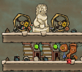
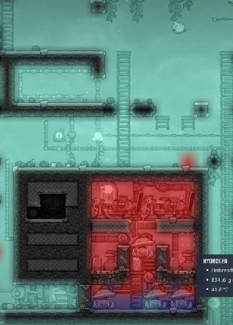
I missed that bit, followed the design exactly and in seconds after firing it up the heat skyrocketed to nearly overload/scalding levels. Shut down 2 of the 4 generators, and it drops to manageable levels again, which can be sped up with ice temp-shift plates. It's possible that it would've equalized just after I shut it down and I just panicked, but there are other comments below indicating their batteries were breaking due to overheat, so I suspect this is the problem.

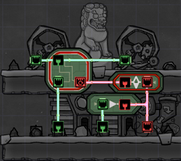
The stage 3 upgrade is still worth it for the automation and microchips though - it's practically a free third generator for the coal of 2 + 10kg of refined metal every 3 days.
LasangeLover421 Mar 24 @ 11:34am 
The "Washroom Sieve Loop" is missing screenshots, pls fix.
Qweef_Latifa Jan 19 @ 4:19pm 
i love you
[TCPIP] Krystal Nov 23, 2023 @ 12:40pm 
To the newer peeps that don't know what gate that is in Coal Generator room stage 2 & 3, its an AND gate
benem Jan 22, 2023 @ 4:04am 
Thank you for the guide. Reveal a lot of mechanics of the game with practical examples.
Anyway maybe is somewhat outdated. The SPOM for example last for several cycles but need to be substituted sooner or later.
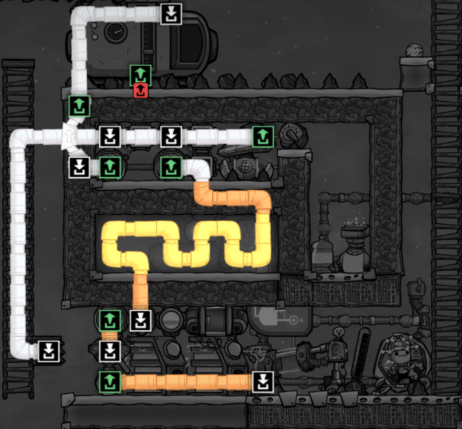
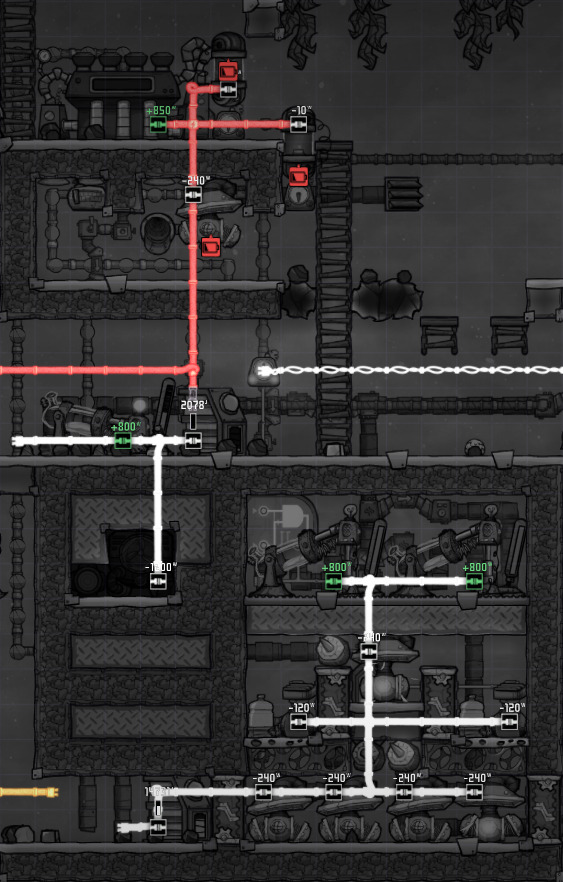
The termperature of the Aquatuner will go up till reach the point of evaporation of polluted water.
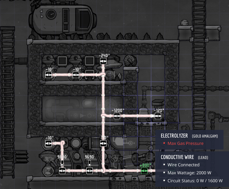
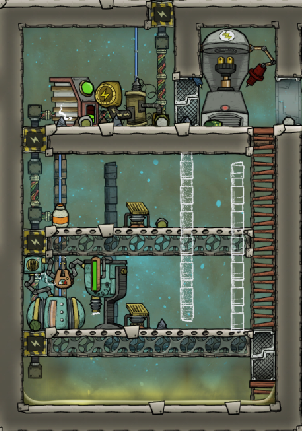
The problem, I think, is that the Electrolyzer doesn't run smoothly due to high pressure and the hiyrogen doesn't flow enough to cool the chamber (the is pipe full of gas at the same temperature of the water for too much time).
That could be the reason of occasional lack of power that need to be provided externally in some way.

Anyway the guide is globally very useful. Thanks again.
AIM-9X Jan 7, 2023 @ 10:39am 
what are the logic gates and sensors in the stage 3 power room? all the models updated and I dont know what each one is
Kaneu Nov 4, 2022 @ 7:45pm 
there still seems to be a lot of missing screen shots. this would help a ton if you were able to reload them. thanks!
tYn0 May 16, 2022 @ 8:44am 
Hi, the "Washroom Sieve Loop" seems to be missing screenshots, could you please restore them?
Thanks :)
Murderhobo Mar 18, 2022 @ 5:24pm 
I'm working on the SPOM and I don't see a value listed in the guide for the liquid pipe thermo sensor next to the aquatuner.

Also I have no idea how much water I'm supposed to use in the steam room based on the description you provided. Why not just list amount instead of having people do math? That's why I looked for a guide lmao