Juno: New Origins

Juno: New Origins

48 ratings
Vectors and PIDs in Vizzy
By mreed2
This is intended to be used by people who learned about vectors while in school, but don't remember the details. In addition, this guide may be helpful to people who know vectors, but are unsure how to use them in Vizzy.

If you don't know what a vector is, this I'm dubious as to whether or not this guide will be useful to you. I include a link to a video series on YouTube that is intended to introduce vectors to laypeople, but... While the production values are great and the illustrations are better, the fact is that vectors are something that need to be studied to be learned properly. Simply watching a YouTube video probably isn't enough in my opinion.

Alternatively, you can copy and paste other people's code to create a frankenstyle Vizzy program that sometimes works, sometimes doesn't, and you have no clue why.
6
   
Award
Favorite
Favorited
Unfavorite
Status
I do not expect to add any more material to this guide, although I will still respond to feedback if there are errors in what is included.

3/31/2024: I believe that all the images are fixed -- if you see references to images (most likely code blocks) that aren't visible, leave a comment, specifying the text that immediately precedes the missing picture.

If Steam decides to delete images in bulk again, I'm doubtful that I'll fix it, but... Do leave a comment to let me know and I'll make a decision at that time.
Introduction to this guide
This guide is intended to be an educational tool, rather than a "Here's the solution, now go off and use it." This is why the main problem solved in this guide (making a "hopper" that can hover under rocket power between two very close points) instead of either of the two obvious much more useful problems (making a rocket that can re-enter to a specified point, or making a rocket that can perform a sub-orbital hop to land at a specific point). I consider the later two problems to be "homework." 😀

This is also why I do not include a craft file that contains all the code shown in the screenshots. Yes, it is a pain to click and drag Vizzy blocks around to match the screenshots, but the act of doing so (and, perhaps even more importantly, the work that you will need to do to troubleshoot the errors that inevitably occur when you fail to follow the screenshots exactly) will, finger crossed, ensure that the reader actually learns why and how all of this stuff works, rather than just blindly following instructions.
Introduction to vectors
As mentioned in the description, this guide is really intended for people that used to know how to work with vectors and just need a refresher.

If you are starting with zero knowledge of vectors (likely if you didn't take Physics in high school, or calculus in college) then the guide isn't likely to be sufficient. This YouTube playlist:
https://youtube.com/playlist?list=PLZHQObOWTQDPD3MizzM2xVFitgF8hE_ab
May help, especially part 1, part 9, and the second half of part 10, and maybe part 13. However, it spends a lot of time on things that simply aren't relevant to vectors as they are used in physics (but are very relevant to using vectors in, for example, 3D rendering) and that may result in more confusion than learning.

If you prefer an actual quasi-textbook, LibreTexts[math.libretexts.org] has an online instruction on this topic. Unlike the 3Blue1Brown video, this tracks more closely with how I use vectors in this guide (e.g. a physics oriented approach rather than a 3D Rendering). However, it doesn't cover changing axis (or "basis", which is the proper mathematical term for what I'm doing).

Feel free to leave a comment if you have a better source for the basics of vectors, or if you the 3Blue1Brown playlist was helpful to you.
Terminology
Scalar
A scalar is a simply number -- for example, "5".

Vectors
Vectors are a scalar (representing magnitude) combined with a direction. The vast majority of people who learn about vectors do so in the context of physics, where vectors are used for velocity, acceleration, forces, and many other values. While it may seem odd, normal cartesian coordinates, such as you may remember using in school to graph a function, can be treated as a vector (and both the game and guide do so). There are advantages and disadvantages of doing this, but that's out of scope for this guide.
The game refers to magnitude of a vector as "length". I'm going to use magnitude throughout this guide unless I'm specifically showing Vizzy code. Both are correct, but I find that "length" invites confusion with "Length of a string", which is totally unrelated to vectors).

Unit Vectors
A unit vector is a vector whose magnitude is always 1. Unit vectors can be thought of as having "direction only", although this isn't really accurate (as they do have a magnitude, its just 1).
To convert a vector from coordinate system A to coordinate system B, you need a set of unit vectors in A. How to get these vectors, and why you would want to do this, is covered later in this guide.

Coordinate System
When working with vectors in 3D space, vectors can be represented in several different ways -- cartesian, cylindrical, and spherical are all common ways to represent vectors. All three methods require an "ordered triple".
  • In the case of cartesian coordinate system all three numbers are scalars representing distance from the origin, such as (x, y, z).
    This is the best system to use when considering motion moving at "human scales" -- if you wanted to represent something moving on or around the surface of a planet on scales small enough that the curvature of the planet can be ignored, this is the right system.
  • In cylindrical coordinate system one angle and two scalars are used, such as (Θ, r, z).
    This is the best systems that where circular motion is present, but only in a single plane.
    For example, if you were modeling a merry-go-round cylindrical coordinates would likely be easiest.
  • In a spherical coordinate system two angles and one scalar is used, such as (Θ, Φ, r).
    The latitude / longitude that we use to measure the position of objects on the surface of Earth (and in the game, as well) is a spherical coordinate system.
This game uses cartesian coordinates exclusively, and while you can generate and store vectors in other coordinate systems, vector operators won't produce the correct results if you do.
Why doesn't the game support spherical coordinates when the bulk of the game is about orbiting planets?

Well, the biggest reason is that the bulk of the effort isn't spent calculating the motion of planets and craft's along orbits. Instead, the bulk of the time is spent converting 3D objects to a 2D picture suitable for display on your screen (rendering), and that activity occurs in an exclusively cartesian coordinate system. From the standpoint of the developers, the amount of work required to build and maintain a separate "model of the universe" in spherical coordinates, re-implementing vector operators to work properly, and conversion routines outweighed the benefit of simplifying the math required.

Another factor to consider is that the game spends a good deal of time dealing with crafts such as planes or rovers. Using spherical coordinates with such craft would be just as awkward as using cartesian coordinates for orbiting bodies. Given that this game is a direct descendant of "SimplePlanes" it isn't surprising that cartesian coordinates are used exclusively.
Math with two vectors at once
In order to draw pictures that illustrate what is happening in an intuitive way, I draw pictures where the origin of vectors is changed. It is important to note that this is simply an aid in visualization, and not an actual change in the vectors involved. All the vectors in the illustration share a common origin at the start of the process and still have that same origin at the end, despite the illustrations showing the origin changing.
Vizzy implements a number of additional operators (beyond what's covered here). Most of them I don't actually know what they do, and the ones that I do understand I don't see any use for. Thus, they aren't covered here.
  • Addition places two vectors "end to end", then returns the vector from the origin of the first vector to the end-point of the second vector. The direction of the vector will be from "from the origin of the first vector to the end of the second vector". Graphically it looks like this.
    "Green + Blue = Red".
    This, oddly enough, isn't very useful. If you know the acceleration of an object, you can add the acceleration vector to the velocity vector to generate the velocity vector for the object in the future, and you can perform a similar operation with velocity and position. However, in practice I have yet to find a use for this in Vizzy programming.
  • Subtraction creates a vector that connects to the end points of the vectors. The direction of the resulting vector will be "from the end of the first vector to the end of the second vector".
    "Blue - Green = Red".
    This, on the other hand, is very useful -- in particular, the difference between two vectors (one "current" and one "target") forms the basis of many PID ("Proportional-Integral-Derivative") feedback loops. This is because the magnitude of the difference (referred to as "error" in this context) drops to zero when the two vectors align, and the direction of the error vectors is highly useful in achieving this goal. There are some example of simple PIDs that use this technique later in this guide.
  • Plain "multiplication" is not possible. Instead, there are two operators that are somewhat similar mathematically.
    OK, technically you can multiply vectors.
    https://youtu.be/htYh-Tq7ZBI?si=QGsoYGmueMF83XgU
    However, despite watching the video I'm unsure of why you would want to. But it is a possible operation.
    • Dot product (·): This takes two vectors and returns a scalar (a number without a direction attached). The value returned will be the length of the first vector that is parallel to the second vector, multiplied by the second vector. Graphically, it looks like this.
      This is, without any shadow of a doubt, the most useful operator described in this guide. If you have a set of unit vectors (three vectors, all of magnitude 1, all at right angles to one another) you can convert a vector from one set of axis to another. This is a key step, for example, in determining what pitch and heading settings will point the craft at a particular object. There is a whole section in this guide devoted to this subject, so more on this later.
    • Cross product (×): A cross product returns the vector that is perpendicular to both of the two input vectors. The direction of the returned vector is determined by whether or not the coordinate system is "left handed" or "right handed" (the one used in this game is left handed). No picture this time -- drawing 3D vectors in such a way that you can tell what the angles are is far beyond my skillset.
      This is of only marginal use in the context of this guide. Through a series of operations, you can take two vectors that aren't at right angles to one another and produce a set of valid unit vectors that can be used transform a vector into a more useful coordinate system. There are a couple of examples of this later.
      The most understandable "mathy" explanation of this is here[mathinsight.org].

      Note that the example shown is correct for a right handed coordinate system because everyone (except Unity) uses a right handed coordinate system.

      If you want to replicate the cross product in the game (for example, to verify your understanding), you'll need to either:
      • Reverse the inputs in the examples (so, when you see "a × b" translate it to "b × a" or
      • Reverse the sign for all the cross products between unit vectors (so, instead of "i × j = k" use "i × j = -k").
      Don't do both -- pick one or the other.
    • Division: Thankfully, no such operator exists -- you cannot divide a vector by a vector.

    Additional operators
    • Angle: This returns the angle (in degrees) between two vectors. Note that two vectors also defines a plane, so a single angle will always suffice to describe the angle between two vectors. The result is a scalar.
      The only use I've found for this is to compare a vector against a unit vector. I use this to determine the pitch angle (as used by the autopilot) that corresponds with a vector.
    • Scale: This returns a vector whose components have been multiplied by the matching components in another vector. Mathematically, this is (X₁ * X₂, Y₁ * Y₂, Z₁ * Z₂).
      This is the same operation as scalar multiplication discussed in the next section -- but now we can specify different scalars for each axis. This is, not surprisingly, useful for scaling a vector.
Math with a vector and a scalar
This is quite a bit more straightforward -- at least when you are dealing with cartesian vectors, which is all I'm going to attempt to cover here.
  • Addition: Add the scalar to the all the components of the vector. The result will be a vector.
    Example: (3, 9, 10) + 5 = (8, 14, 15).
    This isn't used in this guide. It can be used to translate a vector, but the requirement to add
    the same number to all 3 components heavily restricts the possible translations. If you want to add different numbers to each component, you want vector addition (discussed earlier).
  • Subtraction: Subtract the scalar from all the components of the vector. The result will be a vector.
    Example: (3, 9, 10) - 5 = (-2, 4, 5)
    This isn't used either.
  • Multiplication: Multiply each component of the vector by the scalar. The result will be a vector.
    Example: (3, 9, 10) * 5 = (15, 45, 50)
    This is useful for scaling a vector. This can be useful in writing PIDs, although I don't use it in this way. Note that the magnitude of the new vector will be the magnitude of the old vector times the scalar.

    The most useful version of this is to multiply a vector by -1, which will reverse the direction while leaving the vector otherwise unchanged.
  • Division: Divide each component of the vector by the scalar. The result will be a vector.
    Example: (3, 9, 10) / 5 = (3/5, 9/5, 10/5).
    Also potentially useful for scaling.
Unary vector operators
  • "X", "Y", "Z": Returns one of the three scalar numbers that makes up a vector.
  • "Length". Returns the scalar number that is the magnitude of the vector.
    This value will always be positive -- its the result of √( X² + Y² + Z²)
  • "Norm": Returns the vector that points in the same direction as the input vector, but whose length is 1.
    For a vector v, this is equivalent to "v / v.Length", where "/" represents scalar division (as described above) and "v.Length" is the magnitude of v.
Redefining axes for fun and profit
The default (called PCI) coordinate system looks like this:

Note that the Y axis is the one that passes through the poles -- the X and Z axis define the equatorial plane. As odd as it seems, the above diagram is correct.
Its important to note that the definition of axes is fundamentally arbitrary. The game's default axis are relative to the center of the planet whose gravity is affecting the active craft, but it could just as easily be relative to the center of the sun, or relative to the active craft, or any number of other possibilities. The developers simply chose this set of axes because that worked out best from them from a programming standpoint. Nothing stops us from defining and using a different set of axes, if it works best for what we want to do. The bulk of the guide will deal with converting PCI axes into other custom axes, with practical examples along the way.

Converting vectors from one set of axes to another isn't as hard as you might imagine. The trick is to realize that a vector can be represented as the sum of three unit vectors, each of which is multiplied by a scalar. For example, the vector v(10, 59, 333) could be represented as "v = 10x + 59y + 333z" where the bolded characters represent vectors and the non-bolded characters represent scalar values. In the PCI coordinate system the values for the unit are vectors are x = (1, 0, 0), y = (0, 1, 0), and z = (0, 0, 1).
The unit vectors for any set of axes, described using its native set of axes, will always be (1, 0, 0) / (0, 1, 0) / (0, 0, 1). The unit vectors for a one set of axes ("A"), described using some other set of axes ("B"), on the other hand, won't be so simple.

So, the task can be broken into two pieces:
  1. First, we need to create a set of three unit vectors, all at right angles, that correspond with axes that makes more sense in a particular context.
  2. Second, we need to determine the correct scalar values to multiply the new unit vectors by to transform a vector from the old axes to the new.

To take a more concrete example, it would be very useful if the axes for a position aligned with the autopilot control widget. In particular, we would like the unit vectors to point in the following directions:
  • X = 1 meter towards the "North" indicator on the heading alignment circle.
  • Y = 1 meter towards the "East" indicator on the heading alignment circle.
  • Z = 1 meter along the 90 degree pitch line (straight up).
Note that these directions, as measured in the PCI coordinate system, will change as your craft moves. You'll need to recalculate them with each physics tick and therefore re-transform any PCI vectors as well. That's one of the reasons why the game doesn't use such a system as its default, with the other reason being axes like this would make solving Kelperian equations[openstax.org] very hard.

It turns out that Vizzy provides two of the unit vectors we want with no effort on our part.
  • is the unit vector for the "East" direction.
  • is the unit vector for the "North" direction.

Finally, there's a couple of ways to get the "Up" vector, but my preferred way is to use the gravity vector. It's pointing in the wrong direction, so we multiply it by -1 to reverse the direction, then we use the "Norm" operator to reduce the length to 1. This produces , which completes our new set of axes.
Its important to note that our three new vectors use the PCI definitions of "X", "Y", "Z". This makes them "compatible" with any PCI vector that we want to use them with.
An alternate, and superior, way to get the "Up" vector is by normalizing the position vector -- like this . There are two advantages of this method:
  1. You don't have to multiply by negative 1.
  2. This will work on any object, while you can only get the gravity vector for the currently active craft.
I didn't realize this until after I wrote the bulk of this guide, and I didn't want to go through and re-do all the screenshots, so... You'll have to deal with using the gravity vector to define "Up".
Next, we want to convert our vector v to use the new coordinate system. This requires using the dot product, which returns the magnitude of the first vector that points in the same direction as the second vector. Specifically, what we need is this:
  • N = v · North_Unit_Vector_In_PCI
  • E = v · East_Unit_Vector_In_PCI
  • U = v · Up_Unit_Vector_In_PCI
Finally, we can use the equation mentioned above to build a new vector that uses our new axes with "A = N*NEU_X_Unit_Vector + E*NEU_Y_Unit_Vector + U*NEU_Z_Unit_Vector"

Putting this all together, we get the following Vizzy code:
It isn't necessary to place nav(North) and nav(East) into a variable before performing the dot product. I did this for the purpose of making the example consistent with other examples in the guide, where you do have to calculate all three unit vectors.
It isn't necessary to convert the magnitudes back into a vector. You only need to do this if you plan to perform vector math on the NEU vector. Since I do just that, so..
If you do store vectors with alternate axes as vectors, I strongly recommend naming your variables in a way that encodes the axes used in the vector. In this guide I use "NEU", but the important thing is that you are consistent. If you try to perform vector math between two vectors using different axes you'll get an answer (it won't error out), but the answer will be utterly meaningless. This would create problems that are very difficult to troubleshoot, especially since there is no good way to output a vector.

The last statement can be replaced with the "Vec" operator, as follows:
It produces exactly the same results.
Unless you are on a mobile device running 1.0.8 or earlier. Prior to 1.0.9, the vec block didn't work properly on mobile devices. This is listed as fixed in the patch notes for 1.0.9[www.simplerockets.com], but... Mobile releases both tend to lag behind Steam releases and be less frequent to boot. It may be weeks or even months before this version (or a later version) is available on mobile.

If you are on a mobile device, you should avoid the "vec(...)" operator and use vector addition if your version is 1.0.8 or earlier.

If you wished, you could combine all of this into a single step, as follows:
It leads to an awkwardly long expression, but once you've verified that it works you can put it off to the side and treat it as a black box.
The other downside of doing this is that the you end up having to recalculate the unit vectors each time you evaluate the expression. However, Vizzy is fast enough that this is unlikely to be an issue.
Changing the origin of a vector
Some vectors (such as velocity) already have as their origin as the active craft -- but others, such as "Target Position" do not. In order to make the vectors more meaningful, we need to transform them into vectors whose origin lies at the player's craft instead.

Vector subtraction will do what we want. For positions, subtracting the current position of the active craft from the position of the target will produce a vector which, if we treat the player's craft as the origin, will point directly at the target.

In Vizzy code, this looks like this:


Order matters -- the vector that you get back from vector subtraction will start at the position of the second vector and end at the position of the first vector.
If either the craft or the target moves, this vector will no longer be accurate. There is no way to automatically update a vector (or any other value, for that matter), so you'll need to manually recalculate this vector each physics tick that you want to work with the value.

Additionally, note that locations on a planet do move (due to the rotation of the planet), so a variable that stores a vector derived from the location of a grounded craft or base will still change with each physics tick. The "I" in PCI stands for "Inertial", which means that it doesn't take into account the rotation of the planet.

If you convert a position vector into a Latitude / Longitude / AGL triple then the location will take into account the rotation of the planet. Note, however, that a Latitude / Longitude / AGL triple isn't a valid vector by itself, and thus will need to be converted back into PCI coordinates before you do any vector math on it, and this conversion will need to be redone each physics tick to remain accurate.

Still, this can be handy -- you could start with the position of a ground base, adjust the position by (say) 20 km, then convert the PCI vector into Latitude / Longitude / AGL. In future iterations, you could convert the Latitude / Longitude / AGL directly to a PCI vector, eliminating the need to adjust the position each iteration.
Generating "Heading" values
The set(Heading) Vizzy instruction expects a heading from 0 - 360 degrees, with 0 degrees representing due East and 90 degrees representing due North. When using the NEU axes, this problem translates into "Treating the N and E components of the vector as a two dimensional vector, what angle to they produce at the origin". This looks like this:
If you've taken trigonometry this should immediately make you think of the arc-tangent function, and you would be correct. "arctan(E / N)" is the answer, but...
If you actually know trigonometry you are currently screaming at your screen that "No, arctan(N / E) is correct, idiot."

You are, of course, correct. tan θ = opposite over adjacent, and the given the triangle drawn, the correct answer should be arctan(N / E).

However...

You aren't actually interested in the angle contained within the triangle -- you want the angle with the positive East axis. And to get that angle, I should have drawn the picture so that the "North" axis is the adjacent side, and the "East" direction is the opposite side.

More to the point -- arctan(E / N) produces the correct results, so... Shush.

The arctangent function only returns results from 0 to 180 degrees, and we need angles from 0 to 360 degrees. The solution is to look at the signs of the North and East magnitudes before performing the division, then modify the result of the arctangent function as follows:
  1. If both are positive, leave the result alone (returns a value between 0 - 90 degrees).
  2. If North is positive but East is negative, leave the result alone (returns a value between 90 - 180 degrees).
  3. If both North and East are negative, add 180 to the result of the arctangent function (net value will be between 180 - 270 degrees).
  4. If North is negative but East is positive, add 270 to the result of the arctangent function (net value will be between 270 - 360 degrees).
Thankfully, this is such a common operator that the Unity framework developers create a function to automate the process, named "atan2". Rather than taking one input (as arctangent does), it takes two. The atan2 function divides the two inputs, feeds that result into the standard arctangent function, then performs the steps described above to place the result in the correct quadrant. Thus, the answer to our original question is "atan2(East_Mag, North_Mag)".
I think, but do not know, that atan2 also fixes the problem with division by zero. If North = 0 then E / N would be an illegal operation (division by zero). I suspect that the atan2 function detects this and returns the correct result (0 degrees if East is positive and 180 degrees if East is negative).
The developers have decided to expose this function as a block in Vizzy, so this does the trick:
Important: Don't forget the "rad2deg" function call!
  • Some of the built-in expressions that return angles return angles measured in radians. Check the tooltip for the specific functions that you are interested in to verify.
  • All the built-in expressions (such as "sin", "cos", and "tan") that expect angles as input expect the inputs to be measured in radians.
  • All the "Input" type controls (such as "set heading" or "set pitch") that expect angles as inputs expect to receive an angle measured in degrees.
Failure to convert from radians to degrees or vice versa will produce bugs that are frustratingly difficult to troubleshoot. An angle measured in radians that is interpreted as an angle measured in degrees is a valid angle (that varies from 0 - ~6.2 degrees), so your code may produce the somewhat correct result some of the time.

Why yes, I have done that, why do you ask?
If you set the "input(heading)" to the "New_Heading", then the autopilot heading setpoint will point directly at the currently selected target -- that is, it will be aligned with the blue arrow that is visible in the control widget.

Please, I understand its hard to contain your excitement, but try. At some point we'll get to something actually useful, I promise.
Generating "Pitch" values
Pitch is a bit easier to generate than heading -- we can use the "angle" operator with the input vector and the "Up" vector to get the right number, like this.
Why yes, the angle operator does return a result in degrees, not radians, why do you ask?

Consistency is the hobgoblin of little minds, after all.
The most observant among you will be screaming at your monitors that "Hey, you said we can't use PCI vectors in the same expression as NEU vectors, what gives?"

The answer that I'm not -- I'm comparing a vector using the PCI axes (Active_Craft_Centered_Target_Position_Vector) with another vector also using the PCI axes (Up_Unit_Vector). If you tried to do this with "NEU_Target_Position_Vector" you would indeed get the wrong result.

If you replace the last line with this:
It produces the correct results using two NEU vectors. Note that "vec(0, 0, 1)" is the unit vector for "Up" when using the NEU axes.

Now you can aim both the autopilot pitch and heading to point directly at a target. This is more interesting (and better for the purposes of validating that everything is working properly) if you set your target to an orbiting craft. Something in a low orbit works best (because the pitch angle changes relatively rapidly), but Luna will work as well, just turn up time compresion.
Hover Script 1
Now that we know how to bend vectors to our will, we can build a program that makes a rocket hover using rocket engines only.

First, you need to construct a rocket with a TWR at sea level of 1.5 or higher that uses gimbaled engines (any liquid fueled engines). As this is trivial, I won't cover the design here.

The first goal is to calculate how much thrust is required to counterbalance gravity. To do this:
  1. Calculate maximum TWR by dividing "Performance(Max Engine Thrust)" by the current weight of the craft. The weight of the craft is the mass of the craft times the acceleration caused by gravity. Putting it altogether, produces this:
  2. Perform a bit of algebra -- if "t" is the current throttle setting, the current TWR is "t*Max_TWR". If we are hovering, this value should be 1, so "1=t*Max_TWR". Solving for t produces "1/Max_TWR = t", and converting this into Vizzy code produces this:
Putting all this together produces this:
This doesn't quite do what we want -- it ascends forever with constant vertical velocity.

To drive vertical velocity to zero we need a very simple PID ("Proportional–Integral–Derivative") controller. A PID is a function that an input (in this case, vertical velocity) that depends on an input (in this case, throttle) and varies the input in an iterative way to drive the output to a set value. They can be very complex -- but in this case, we can get away with a very, very simple controller. All we need to do is:
  1. Determine the magnitude of the error.
  2. Scale the error to match our input parameter.
  3. Modify our "zero point" (the input value expected when the system is at equilibrium) by our scaled input number.
Converting this to our specific problem, we need to:
  1. Subtract current vertical velocity from target vertical velocity.
  2. Multiply the result of the previous step by a scaling factor. This will be a "magic number" -- that is, you'll need to hand tune this value to take into account a variety of factors, including
    1. How quickly you want to drive the error to zero. Very high scaling factors will result in extreme reactions to small errors in velocity.
    2. How fast the actual thrust changes when you change the throttle setting. This depends on what engines you use.
    3. If velocity is high enough, the effects of drag on the craft.
    While this example uses a simple operator (multiplication) of a single input value. You can design a PID that takes multiple input value (for example, the settings of several different control surfaces, measured independently) and apply a complex function to drive the expected results. This is the "hard" part of designing a PID, and even in the real-world lots of iteration is required to produce the right results in all cases.
  3. Add the result of the previous step to our previous calculated throttle.
Implemented in Vizzy, it looks like this:
To reiterate again -- the scaling factor (named "Vertical_Gain") is purely arbitrary. Your rocket will probably need a different value. Try different values to see what works best for you!

After playing with it, you'll notice a couple of issues:
  1. First, a small amount of lateral velocity appears the longer the script is running. This is caused by small errors in the simulation -- without a PID to manage horizontal velocity, these small error eventually result in a small amount of lateral velocity.
  2. The vertical velocity never actually reaches the target value. This is a known issue with PIDs of this type, and the fix is to make the PID function more complex, either by taking into account the integral of the current value (acceleration in this case) or the derivative of the current value (altitude, in this case) as additional factors in the formula. Feel free to play with the equation that produces "PID_Vertical" to see if you can improve the performance.
Much later, this script will be used as a component of a larger PID that lands at a target. When used in that mode I end up modifying this PID to take into account altitude, which corrects the issue.
Hover Script 2
Some people will have noted that, so far, we haven't made use of any of the techniques we covered earlier about converting the axes of vectors to a new coordinate system. Fear not, because we'll need to do this to add lateral control to our hover script.

In order to control lateral velocity, we need to:
  • Describe in some way the desired or target horizontal velocity. I use a vector for this purpose (and include the vertical target velocity as well). An alternative way to do this would be to simply use two variables ("North_Target_Velocity" and "East_Target_Velocity") along with the existing vertical target velocity variable.
  • Determine the error between our current horizontal velocity and target horizontal velocity.
  • Set the proper heading to cancel out the error.
  • Calculate and set the correct value for pitch. The greater the error in our lateral position, the lower the pitch should be -- but we need to ensure that the value doesn't drop below the point where we no longer have enough thrust in the "Up" direction to counter the effects of gravity.
  • Set the throttle to the proper value to manage vertical velocity at our non-90 degree pitch setting.
The last is easiest, so we'll tackle that first. We already have a formula that works for Pitch = 90°. We could start drawing triangles and the like to work out what proportion of the thrust is going upwards (versus laterally) at other pitch settings.

Or....

We could realize that "Hey, this has to be a trig function, and sin(90°) = 1 while sin(0°) = 0, so that must be the right trig function to solve this problem."
Important: This code never ends up being used for anything beyond display -- I use a PID to set the throttle properly without referencing this value. As a result, this value was incorrectly defined -- I defined it as "sin(pitch)/Max_TWR." I didn't realize this until it was pointed out in a comment.

I've corrected the code here, and in the following screenshot. I have not corrected the code throughout the rest of this guide, largely because it would take ages to reconstruct the code for no functional benefit.

But, yeah, the above code is correct.
The maximum safe pitch is the pitch value that requires 100% throttle to achieve 0 vertical acceleration. We reason as follows:
  1. We will want an inverse trig function, and since we just worked out that we needed sine for the previous step, this must be arcsine.
  2. The length of the hypotenuse of our triangle will be "Max_TWR", because first we are assuming 100% throttle (so Max_TWR = Current_TWR), and the length of the hypotenuse represents the full thrust of the engine.
  3. The vertical component of the triangle should be 1 as we want a "Vertical TWR" of 1.
  4. Because of how pitch is defined in the game, the vertical component will be the "opposite" side of the triangle.
  5. Therefore, arcsine(1/Max_TWR) will return the value we want.
Putting all of this together, we end up with this:
You can now manually adjust the pitch and heading of the rocket to change the lateral velocity, without interfering with the rockets ability to maintain vertical velocity. Well, as long as you don't set the pitch too low, that is. You'll note that the "Min Safe Pitch" value shown goes down as the rocket hovers, and that's as expected. As fuel is burned off maximum TWR increases, and thus the rocket can accept a lower pitch angle and still maintain vertical control.

The next step is to convert the PCI surface velocity vector to NEU. We've already done this, so lets convert this into a parameterized custom expression -- that way we can call it with an arbitrary PCI vector and get back tne NEU equivalent.
Note that I changed up the variable names, simply to keep the (alphabetized) list of variables more organized.

If you need to convert several vectors using this stored procedure, you'll need to copy the output variables into dedicated variables between calls. That's the downside of using global variables as return variables, after all.
While we are at it, lets write up another custom expression to convert any cartesian vector to a spherical vector. Vizzy code:
Unlike the previous implementation, which used a mix of PCI and NEU coordinates, this code converts cartesian to spherical while preserving whatever the axes are of the input vector. As a result, the variables names have been changed to be more generic, which also helps keep the variable list organized.

In addition, the "90-" has disappeared (when calculating "Spherical_Phi"). That's because, mathematically, φ is defined as the angle between the Z axis and the vector. For reasons that likely have something to do with Unity, the game defines the pitch of the craft as "90 - φ". Since I was testing the code by targeting a satellite and setting the heading and pitch angles to match the results of my calculations, I naturally gravitated to retaining this convention.

The problem is that you can't use the standard formulas to convert from spherical back to cartesian (which is covered much later) if you define φ this way. So, I changed the code here to make life easier later.

Note that if you do want to test the code, you can still easily get a valid pitch angle from it -- just set the pitch to "90-φ" instead of using φ directly.
Note that while it does store the output in a "vector", if you try to use this as a vector with the built-in functions you will get incorrect results. The built-in functions are hard coded to expect a cartesian vector.
We put it all together and we get this:
All right, all right, we'll go over this in a bit more detail.
Hover Script 3 (aka How to use the "Display" command in Vizzy)
First, the easy part -- displaying status / debug information.
These are just two strings that will be feed into the Vizzy format widget later that display a wide range of variables in a user friendly format. Some specific notes:
  • "{0:n4}" means "Replace this with the first parameter, formatted as a number with 4 decimal places.
  • "{0,8:n4}" means "Replace this with the first parameter, formatted as a number with 4 decimal places, padding with leading spaces so that the total string is 8 characters in length."
  • "<br>" means "Start a new line here".
  • "<pos=10%>" means "Move to the right 10% of the maximum space available."
  • You can insert newlines into a formatting string by copying and pasting a new line character from Notepad.
  • More to the point, you can setup an entire formatting string in Notepad, then copy and paste the result into Vizzy, and it works properly (which, of course, is what I did). If you need to edit the formatting, just click once on the string in Vizzy (which will select all of it) and copy and paste it back into Notepad.
  • There is a limit (likely 256) to the number of characters that can be stored in a string literal. Thus, I needed to split the formatting string in two.
You can find more information about the special "quasi-HTML" tags you can use here[docs.unity3d.com] and you can find information on how to format numbers here[learn.microsoft.com], although the Microsoft site doesn't mention the ",X" syntax to pad with spaces. Its probably on a different page.

The full format strings (if you want to steal them for your own script) are:
  1. <br><br>Hover Status<br><br> Velocity<pos=10%>Current<pos=20%>Target<pos=30%>Error North<pos=10%>{0,8:n4}<pos=20%>{1,8:n4}<pos=30%>{2,8:n4} East<pos=10%>{3,8:n4}<pos=20%>{4,8:n4}<pos=30%>{5,8:n4} Up<pos=10%>{6,8:n4}<pos=20%>{7,8:n4}<pos=30%>{8,8:n4}
  2. <br>Outputs Heading<pos=10%>{0,8:n4}<pos=20%>{1,8:n4}<pos=30%>{2,8:n4} Pitch<pos=10%>{3,8:n4}<pos=20%>{4,8:n4}<pos=30%>{5,8:n4} Throttle<pos=10%>{6,8:n4}<pos=20%>{7,8:n4}<pos=30%>{8,8:n4}

The output portion (where the format strings are actually used) is found near the end of the loop, and looks like this (when not cut off).
Reminder: You can click on a picture in a Steam guide to view that picture in a separate window. Its still not very readable, but... Its better than the thumbnail that appears above.
This is what it looks like in flight mode:
To produce more meaningful output, I created two utility expressions:
This converts an angle to fit into the range from 0° - 360°. It does this by dividing by 360 and returning the remainder (called the "modulo" operator, and represented in computer programming with "%"). This only gets us to range between -360° - 360° -- to achieve our desired range, we check to see if the value is negative, and add 360° if it is. This produces an angle that matches up with the angles returned by the nav(heading) / nav(pitch) components, and is, generally, more human-friendly.
Note that the game will happily accept negative angles or angles greater than 360°. It performs a similar operation automatically, but you can't access the results directly.
Finally, we have this:
When you subtract two angles there are always two possible results (actually, there's an infinite number of results, but two "obvious" possibilities). One is that you figure out the angle traveling clockwise from the first angle to the second, and the other option is the angle traveling counter-clockwise from the first angle to the second. More often than not, you are interested in whichever angle is smaller rather than preferring one direction or another. This expression calculates both, forces the angle to be positive, and returns the smaller result.
This also handles angles that straddle 0° in an intuitive way. Generally, you expect "10° - 350°" to produce "20°" rather than "340°".
None of the above is actually required for the hover script, technically. However, debugging the script will require something to provide feedback to the developer as to the internal state of the code, and hey, pretty things to look at! 😀😀
Hover Script 4
Starting from the top:
  • Unchanged from previous iterations -- we need to spend some time going straight up to avoid terrain / get off the launchpad.
  • Both the gain and target values are changed to vectors. This allows us to control the gain on each of the axis independently, and we need to be able to set target values for each of the three axis independently as well.
  • I increased the amount of time it waits before starting the loop, as I wanted more height to avoid terrain. How long you should wait depends on where you are doing the testing and what the starting TWR of your rocket is.
  • These lines have already been covered in detail elsewhere.
  • The definition for "Convert_PCI_Vector_To_NEU" was covered in part 3.
  • The next line performs vector subtraction on the target velocity vector and the current velocity vector (NEU_Vector, which was set in "Convert_PCI_Vector_To_NEU") to produce an error vector. We then multiply ("scale") this vector by the gain vector.
    The scale operator is equivalent to "vec(X₁ * X₂, Y₁ * Y₂, Z₁ * Z₂)."
    The PIDs ultimate goal is to drive the magnitude of this vector to 0.
  • Then we calculate the length of error vector projected onto the XY plane. In English, this is magnitude of the error ignoring any vertical ("Z") component.
    You can replace this line with:
    This implementation is probably faster than the implementation shown. I chose to do it the way that I did because the "sqrt" statement is compatible 1.0.8 and earlier on mobile devices, where the "VEC" operator isn't reliable.
  • Finally, we convert the velocity error vector into spherical coordinates.
  • Next up is setting the desired heading to "Spherical_Theta". This is defined as the angle of the vector on the plane described by the North / East axis, treating the East axis as 0 degrees, measured counter-clockwise. In less fancy terminology, theta was originally defined to be used as a heading input, so of course it can be used as such.
  • Next, we set the target pitch to 90° - the magnitude of the scaled horizontal error.
    Wait, I hear you say -- "Hover_Lateral_Error" is measured in meters per second, but you are treating it as an angle.

    Yeap, that's exactly what I'm doing. Ignoring units in this way is fairly common in PID design. All I care about is that the pitch angle decreases as the magnitude of the error increases, and when error reaches zero pitch is set to 90°. Simply subtracting the lateral speed from 90° achieves that result, and ultimately that's all that matters.
  • Finally, we set the throttle to the throttle required to cancel out the effects of gravity (at our current pitch) plus the error in the Z direction.
  • And, finally, we tell the built-in autopilot what we want it to do.

Whew, that's a lot of work. I recommend you spend some time playing with this code, by adjusting the Gain_Vector and Target_Velocity values to see how your craft responds to different values. Some notes based on my experience:
  1. It never manages to get the error for lateral velocity very low -- it ends up with an error of 0.45 and 0.14 for East velocity. These numbers aren't as bad as they seem at first glance, because that's the error after scaling has been applied, and I've got the lateral gain set to "5". So the actual error is only 0.09 m/s North and 0.03 m/s East. I believe the source of this error is drag (which shows as 0.12 m/s²) -- the code isn't aware of this acceleration, and that throws off its calculations.
    I'm not really satisfied with this answer because the error increases with time, rather than remaining constant.

    However, this code, when called from a "Fly to position and land" routine, does work -- and, despite spending a few hours on it, I can't find either an error or an alternate solution. So... Good enough?
  2. Along the same lines, once the craft is stable (heading in the desired direction at a mostly unchanging velocity) the heading vector doesn't align with the surface velocity vector. I believe that this is also due to drag -- in particular, the unequal drag caused by having a higher "North" target speed (10 m/s) vs "East" speed (5 m/s). The higher speed in the North direction results in higher drag in that direction, which the script recognizes by consistently biasing the heading in the North direction.
  3. Immediately after the initial boost stage completes, the script will command a negative throttle. The game ignores this, of course, and the throttle gets set to zero. Once the upward velocity imposed by the upward movement drops to close to zero it throttles up -- and then proceeds to request a throttle greater than 100%, which the game also ignores. It'll settle down to a stable throttle after some oscillation (how much depends on how high the gain is on the throttle -- a high gain = more oscillation). This is one of the reason you get away with just adding a velocity to a percentage based value -- yes, you'll get out of range values, but the game will clamp the values to the right range, and as long as things work properly...
  4. The script will set heading and pitch angles even when the engine is turned off. Assuming you have gyroscopes installed on your craft, the autopilot will still move the ship to point in the commanded direction. On the plus side, this ensures that it is pointing in the correct direction when the engine eventually throttles up -- on the other hand, it changes the aerodynamics of the craft, which may result in unwanted lateral velocities being introduced. If you are curious, this is a possible area of improvement.
  5. Finally, this script prioritizes managing lateral velocity over vertical velocity. If you are using this script as a component in a "Land from orbit" script you may want to add an "If velocity(vertical) < -100 then new_pitch = 90" line to ensure that it manages extreme vertical velocity before worrying about horizontal velocity.
Hover and land at target
The next step is to wrap all the code that we've written so far into a custom instruction and add some parameters.
This, of course, isn't necessary -- but it helps keep the code organized. Some comments:
  1. The target velocity and gain vectors are now parameters, and the relevant statements reference the parameters rather than the global variables we were using up to this point.
    Don't forget to update the massive format status string!
  2. I've added a boolean to turn off the display of status information. Note that it still generates the status string, it just doesn't display it. We'll use this to prefix position information on the same string.
  3. I've added another boolean to disable actually executing the heading, pitch, and throttle commands generated by the code. The new values are still calculated, just not executed. While I don't use this, I can easily imagine someone wanting to use the hover script as part of a more elaborate script, where having these values set to "reasonable" values might simplify the extra work that needs to be done.
  4. Finally, I didn't include the loop in the custom instruction. This allows the caller to update the parameters (in particular, target velocity) with each iteration, and that's exactly what we are going to do with our precision landing script.

Next, we need to write another PID to drive our position error to zero.
This should look very familiar at this point, and therefore I'll only go over it briefly.
  1. First, we get a PCI vector that points from the active craft to the target.
    Note that this vector completely ignores such minor things as terrain, or the planet. Since this is only going to be used if we are close to the target, that's fine.
  2. We convert the relative position vector to NEU axes.
  3. We calculate the lateral error.
  4. We apply a scaling factor to the NEU error vector.
  5. If we are close (< 100 meters, but > 1 meter) we start a gradual (10 m/s) descent to the target, stopping the descent at 100 meters above ground level. This is all but required because of the rotation of the planet -- while small, hovering 500 meters above the target requires enough extra lateral velocity to prevent the script from driving the position error to the desired level.
  6. If we are very close to the target (<= 1 meter of lateral distance), we land.
  7. Otherwise, we set the vertical velocity requested to 0 m/s, to maintain altitude.
  8. We generate a status string.
  9. Finally, we concatenate our status string with the status string generated by the "Three Axis Hover" custom instruction, and display it if that option was selected.

The main loop looks like this:
There isn't much that's new here. To point out some highlights:
  1. We, of course, have a new massive formatting string. If you want to steal it for your code, I used:
    Position Status <pos=10%>Current<pos=20%>Target<pos=30%>Error North<pos=10%>{0,8:n4}<pos=20%>{1,8:n4}<pos=30%>{2,8:n4} East<pos=10%>{3,8:n4}<pos=20%>{4,8:n4}<pos=30%>{5,8:n4} Up<pos=10%>{6,8:n4}<pos=20%>{7,8:n4}<pos=30%>{8,8:n4}
  2. We have a new gain vector. You'll want to set the numbers, especially the X and Y components, to something very small. Distances measured in meters are large, and after scaling this number will be used to set the target velocity for the hover script. Yes, this means that if the target is 1000 meters away, the target velocity will be 1 km / second. It won't achieve this this velocity, of course, but high gain will result in lots of oscillations as it overreacts to "small" (say, 20 meters) errors by generating maximum horizontal acceleration, overshoots the target, then tries to correct.
  3. Rather than running the loop forever, we loop until the grounded flag is set.
  4. I finally remembered to add the "Wait 0 seconds" to the loop, so it doesn't pound the CPU harder than it needs to.
  5. Finally, make sure you turn the engine off.
That's all there is to it, honestly.

This is the situation where the autopilot kicks in.

The autopilot has just decided to start reducing lateral velocity.

The autopilot has decided to start descending.

Landed!
Things to try:
  • Calculating the distance to the target once (just before you start the guidance loop) and using this to adjust the gain used by the landing program. Right now, the "right" value for gain depends on the distance to the target in addition to craft specific parameters, so adjusting it might make it "less magic".
  • Alternatively, store the initial error vector, then use the initial error vector and the current error vector to calculate a "percentage error". This will result in a vector whose components range from 0-1, and that means that when you can treat the landing gain vector as "Maximum velocity" vector. This would get close to converting landing gain to a "non-magic" number.
  • Modify the hover script to maintain a constant altitude above terrain rather than a constant altitude above sea level. To make it work properly, though, you would actually need to find the altitude ahead of the craft, not what's just underneath, and that's tricky. A good place to start would be converting the craft's current position into latitude / longitude / AGL coordinates, bump latitude / longitude a very small amount along the direction of travel, then use the "Get terrain [height] at lat/long" block to see what the altitude is. If the terrain is higher than the ground directly under the craft, add vertical velocity -- if its less, reduce vertical velocity.
  • Add landing legs and try landing with higher vertical and horizontal errors. The current script is very conservative, and much faster landing (= less fuel used) are possible.
  • Along the same lines, rather than trying to land at the target, modify the code to start nulling lateral rates as soon as the distance to the target is less than a certain value. Such a solution could save lots of fuel, at the cost of lots of error in the landing position.
  • Add at least one more stage, write code to launch onto a ballistic trajectory that ends up close to the target, then use the "Hover and land at target" routine to land exactly on target. This is one of the ways to complete the Drone Ship landing mission, which is required to unlock the DSC small pad.
  • Convert this autopilot to work with a plane. The same principals apply, after all, but you'll need totally new expressions to vary throttle and pitch to control vertical speed.
Hover Script 5
You might wonder if you can hover better if you use acceleration to drive the PID rather than velocity. Well, wonder no longer:
This is designed to function as a "plug-in" replacement for the previous custom instruction, although you do need to add an additional parameter when you invoke it.

The bulk of the code is the same -- the new code works as follows:
  1. Calculate the acceleration of the craft. This is simply a matter of subtracting the current velocity with the previous velocity, all divided by the amount of time that has passed since the previous velocity timestamp was captured.
    The goal of the if statement is to allow the loop to initialize properly without needing a dedicated variable to do so.
  2. The next step is to calculate the acceleration targets. This is done by scaling the velocity error vector (which we calculated earlier) by the acceleration gains.
    This, I believe, is correct -- at least, I can't come up with a way to go from position to acceleration targets that doesn't "pass through" velocity along the way. You could do it all in one step, of course, but that doesn't change the fact that you are calculating velocity. "Change in position over time" is velocity, after all.
  3. Then we do the same thing that we did previously with the velocity vector (calculate the error and calculate the lateral component) but with the acceleration error instead of the velocity error.
Don't forget to set the "Hover_NEU_Accel_Gain_Vector" in the main loop.
So, what's the verdict? It doesn't seem to matter a great deal, honestly. With a bit of tuning the acceleration based script (accel_gain = (2,2,1); vel_gain = (1,1,0.1); pos = (0.1, 0.1, 0.1)) performed slightly better (measured by "Amount of fuel left at landing") than the velocity script (vel_gain = (2,2,0.1); pos_gain = (0.1, 0.1, 0.1), but... The margin was 1% of fuel, and I'm pretty sure that I could have achieved the same result with the velocity hover with by further refining the gain values.

I think the acceleration based script may be more robust -- that is, it will produce better results without being hyper-tuned for the situation that it is being tested in, but I can't think of a way to test it. If you want to tinker with a non-linear gain, I think it may work better with the acceleration script as well.
A non-linear gain seems to be the best way to further improve performance. You want to delay canceling out lateral velocity until the last minute, at which point you thrust at the minimum pitch angle opposite the velocity vector, hitting zero lateral velocity directly above the target. You want a function that is shaped like a normal distribution[en.wikipedia.org] where the "peak" (maximum response) covers the range 5-10 m/s (or m/s^2). Outside of this range, you want to default to a linear function similar to what is being used today, but in that peak you want to command much larger pitch angles than the current linear function produces. Implementing and testing this is left as an exercise to the reader, though.
For the purpose of the remainder of this guide, it doesn't matter which of the two hover implementations that you use, so pick the one that works best for you.
Landing site re-designation 1
An improvement that I'm actually going to implement is a Apollo style P64 "Landing Site Re-designation". If this doesn't mean anything to you, a brief explanation can be found
here[www.hq.nasa.gov]:
Originally posted by Apollo: GNC by Allan R. Klumpp, page 19:
...By manipulating his controller left, right, forward, or aft, the commander directs the LGC to displace the landing site ( and the P64 targets) along the lunar surface by a correspondingly directed fixed angular increment ( 1 ° ) with respect to
the current line of sight.
The LGC redirects the thrust to guide to the redesignated (now current) site, and reorients about the thrust axis to maintain superposition of the reticles on the current site . The commander can continue this redesignation process - steering the current landing site into coincidence with his chosen site - until 10 seconds before reaching the P64 target point, at which time P66 is initiated.
The goal here is to allow the player to, realizing that he/she is about to land on a 45° slope, to push "forward" and have the targeted landing site move, well, forward a small distance (say, 50 meters). He/she can repeat this as many time as needed to shift the landing site to clear terrain, then allow the autopilot to land at the new target.

Breaking this into its component parts, there are two main tasks:
  1. Adjust the target point in response to the inputs.
  2. Capturing user input without interfering with the autopilot.
The first issue is harder than it looks. The primary problem is that... Well, the planet is curved did you know that? Any cartesian system (say, the NEU axes) isn't going to follow the curve of the planet, and that means that the target point won't actually match what the user selected. And before you say "Well, its mostly flat, at least within (say) 1 km or so," this game has some itty bitty bodies to land on. T.T. only has a radius of 23 km, and Handrew's Comet has a similar radius. Assuming a flat plane on bodies with such small radius will produce enormous errors, large enough errors to render the system useless. Of course, you could use math to adjust the aimpoint to follow the curvature of the planet, but that would be hard (and the whole point of this guide is "How to use custom axes to make things work in an intuitive way").

The next obvious solution is to convert the current landing site to latitude / longitude, then redesignate the landing site by increasing / decreasing the raw latitude / longitude numbers. This... Almost works. Breaking this problem down, the circumference of the planet is 2πR. And that means that "degrees per meter" is "360/2πR". If you take a distance measured in meters, multiply it by the "° / m" and have the answer that we want.

Except...

One degree of longitude isn't constant -- it varies, and it varies with your longitude. The right formula for longitude is "(cos θ)*(360/2πR)", where θ is your current longitude. But as your longitude increases the result of this formula changes. The more mathematically inclined among you are now saying "Hey, an integral will solve that in a jiffy," and, yeah, you are correct. If you want to approach it this way, more power to you (a good starting point is the formula "dist_between_two_points_on_a_sphere = 2R × arcsin(sqrt[sin²((θ₂ - θ₁)/2) + cos(θ₁) × cos(θ₂) × sin²((φ₂ - φ₁)/2)])", where (θ₁, φ₁) and (θ₂, φ₂) are two points on the surface of a sphere, θ is latitude, and θ is longitude). However, the point of this guide is to show how to use axes to make hard problem easier, not just how to solve problems, so that's out.

Well, we could just use the formula for "° longitude / m" at the target point, then assume that the factor remain constant -- surely that would be good enough. But it isn't good enough -- at least, not when you are close to the poles, as a simple Vizzy program will illustrate:
Just build that program on a stand-alone command disc, then go into flight mode and designate various targets on Drool. You'll see that the distance is very, very different close to the poles (there's a target at the South Pole and "Amundsen Ground Station" that is nearby. A solution that only works sometimes isn't good enough -- we need something better.

Well, the orientation of the latitude and longitude grid is "arbitrary" -- there is no reason we couldn't re-orient the axis to make this problem easier to solve. Oddly, the easiest solution to the problem is to orient the spherical axis so that the Z axis passes directly through the target location. Yes, that's odd since it ensures that the target is always at the pole, but... There's method to this madness. If you are sitting at the pole, your longitude [θ] (if it means anything at all) indicates what direction you are facing, and your latitude [ϕ] represents how far you are from the pole. If you proceed to travel 1 km along the 45° line of longitude, then your latitude is ("Distance from the pole" / "Circumference of the planet") / 360°. This is exactly what we are looking for -- an easy way to convert a direction and distance from a certain point into valid spherical coordinates.
Landing site re-designation 2
The DLU code presented here doesn't produce the correct results in practice -- but it is close, and I can't figure out what's wrong despite spending hours fiddling with the code and asking the discord.

The issue is that, assuming the two reference points (target and active craft positions) are stationary with regard to one another, moving the target point in the "Left Crossrange" direction should produce a circle. But it doesn't -- it produces a spiral. As a consequence of this, the Downrange direction is also incorrect -- re-designating the target 50 meters downrange, then 50 meters uprange, doesn't leave you at the original point.

Given the failure mode, the issue is almost certainly in the definition of the left crossrange unit vector. But the definition should be correct.

Its worth pointing out that the code that glues the new PCI point to the ground signficantly increases the magnitude of the problem, but the issue remains without it.
The first part of solving this issue is to identify a "target-centric" set of axis. The current set of axes that we have won't work for this problem, because North / East / Up are all defined relative to the active craft. We need to define a meaningful set of axes that are relevant to the target, so we can displace the target in a controlled, intuitive way.

This is the set of axes I will be using:
  • Z will be norm(Target_Pos).
    This points in the up direction as defined from the target perspective.
  • Y will be norm(Target_Pos - Reference_Pos) ⨯ Z
    This is at a right angle to the plane defined by the vector pointing straight up at the target and the vector that connects the target to the a "reference position" -- in many cases, the "position of the active craft" is the right value to use for the reference, but for testing we want this to be the "initial position of the active craft."
    If you align the Y axis with the vector from the target to the active craft, your Y value will always be zero if you convert either the PCI vector that points at the active craft or the PCI vector that points at the target. This behavior will be highly useful in solving the underlying problem.
  • X will be YZ
    This is at a right angle to both of the other two unit vectors, and completes the coordinate system.
Note that calling "X" downrange is slightly misleading. X measures downrange / uprange distance ignoring the curvature of the planet. Without using spherical coordinates, that's the best we can do.
Important: While I call these vectors DLU, a key part of the definition of these axes are the values of "Reference_Pos" and "Target_Pos", as they are defined using the PCI axes. If you create a DLU vector with one set of values for "Reference_Pos" and "Target_Pos" and a second DLU vector using a different set of values for "Reference_Pos" or "Target_Pos", the two vectors aren't compatible. This is true of all the vectors that we create by axes conversion -- its just more obvious here.

The most likely reason for this to occur is because your Vizzy code "ran long," and a physics tick occurred when you didn't expect it (specifically, at a "wait 0 seconds" statement). If the physics tick is changing unexpectedly and you can't make your code more efficient, the easiest solution is to insert a "wait 0 seconds" at some logical point in your code. As long as you know the physics tick is occurring at a specific instruction you can generally code around any problems that might occur.

Keep in mind that if multiple craft (or components, or threads within a single component) are all executing at the same time, all of those Vizzy instructions are pulling from one "common pot" of instructions that can be completed in one physics tick. So, your code might complete in a single physics tick during testing (where only your code is running) but take multiple physics tick when other craft / components / threads are active.
It isn't necessarily a disaster if a physics tick occurs while your code is running in any case -- yes, you'll have some incompatible vectors, but they will be close, in any many cases close is good enough.
We also need to come up with better names for our axes, and a TLA (so we can name variables properly). "Downrange / Left crossrange / Up" (DLU) seems workable.
We also need to test this, so a quick test program:
Comments on the testing program:
  1. The current target velocity passes by Ali Base to the right (so the crossrange will be negative). To pass to the left, change the "-20" to "50".
  2. LLA is now the official TLA for "Latitude / Longitude / AGL" vectors.
  3. You need to store the initial position as an LLA vector, then convert it back to PCI each time you use it. Otherwise, it won't take into account the rotation of the planet.
  4. Z ("Target Up") includes the radius of the planet in addition to the altitude of the target as measured from the reference position. For the purposes of displaying a "reasonable value", I'm subtracting the radius of the planet. If, and only if, you are directly above the target this calculation will produce match "ASL". However, if you are distant from the target, this component is measuring your distance above or below the X / Y plane defined by the unit vectors. In particular, this plane is, well, a plane and won't reflect the curvature of the planet.
  5. If you use the current position of the craft as your reference position, the Y component will always be zero. This is actually correct behavior -- if the vector to be converted and the reference vector are the same vector, then its impossible for any crossrange to exist. In many, perhaps even most, contexts this is fine, but for testing purposes it doesn't work out very well.
Next up is testing with the autoland at target script.
This is basically the same as the previous version, with the addition of code to calculate and display the DLU vector. It works as expected, showing (0,0,ASL) when landed at the target. If you wanted, you could use the DLU axes instead of NEU reference to make a hover script -- but be warned, the Up component in DLU is defined relative to the target rather than the active craft, so you'll need to manage vertical speed differently.
Landing site re-designation 3 (aka "Floating Point Math Sucks")
The next step is to write a custom instruction to convert a DLU vector back to the PCI axes. This is easy, if a bit odd.
Remember, to convert between axes, we need a set of unit vectors for the target axes converted into equivalent vectors expressed in terms of our current unit vectors. Since we have a custom instruction to convert a vector into DLU, we just call that -- but specify the vector to be converted as the PCI unit vectors. Since these vectors are just (1, 0, 0) / (0, 1, 0) / (0, 0, 1) we get the code above.
This is horrifically inefficient -- for each call to this custom instructions, we are calculating all three of the DLU Unit vectors three times, even though they are (hopefully!) unchanged. A much better solution would be to move all the code that generates unit vectors into its own dedicated custom instruction, then call that custom instruction once per physics frame. The easiest way to do this would be to place the "Update_All_Unit_Vectors" call immediately after the "Wait 0 seconds" statement in your main program loop.

I don't do this here because it makes the code much less readable.

Whatever you do, don't put the code to update your unit vectors in its own thread (by attaching it to a second "On Start" event). You'll have no way of telling whether or not all the unit vectors have been updated for the current physics frame when you call a custom instruction that references them, and if they aren't, or (worse still) they have only partially updated you'll get weird, intermittent cases of things "not working quite right." And these problems will become more serious the faster the craft is moving, as higher speeds will result in larger changes to unit vectors per physics tick. Just don't do it. There's no speed advantage to having multiple threads (even if you use multiple components or multiple ships) as there is a single Vizzy process that switches between all active Vizzy processes, executing one instruction at a time.

There are many circumstances where having multiple threads isn't harmful, or even is beneficial (and there will be many examples of this later), but "Initializing unit vectors for axes conversion" isn't one of them.
We also need a custom expression to convert spherical coordinates back to cartesian.
This, I must confess, I pulled directly off of the Internet rather than working it out from first principals. Thus, I can't really say that I understand why it works, although I have a vague idea. If you need to know, you can look it up for yourself.

And now, all good things must come to an end. We need to test the code that we wrote -- specifically, we need to verify that PCI->DLU->Spherical->Cartesian->PCI works properly. So, we have this:
Here is the full text of the output line:
Now, a poll -- how many people understand why I knew before I even wrote the code that it would be a problem?

No, its not because I was sure there were bugs in the code. Believe it or not, the new code worked properly in all respects on the first attempt. I did discover a bug in the Cartesian to Spherical code (which was mentioned much earlier) that didn't matter until this point, but even that turned out be minor.

No, its something altogether different. Everyone made your guess?
These are screenshots of the output of the program at various stages of running its code (in chronological order, so the 1st image was taken when the craft was as far away from the target as it was going to get, and the last was taken while the craft was sitting on the ground).

Floating point precision errors strikes again.☹️

For those who don't know, floating point numbers have finite precision -- but the output of various mathematical operators (especially trig functions) require unlimited precision to be accurate. For example, sine is commonly defined as an infinite series of fractions. When you ask a computer to do perform a calculation, it calculates the result out to some number of digits and then... Well, it just stops. In the case of the game, it looks like there are 17 significant digits, which seems like plenty, but... It isn't, really. The errors tend to compound, you see -- the first number was only off by 0.00000000000000001 but then you multiplied it by another number that was off by -0.000000000000000001 and multiplied it by 50, and divided it with another number that was off by 0.000000000000000001, took the arccos of the result, and so forth.

There's a lot of trig going on behind the scenes -- each dot product involves a trig function, cross products involve several, and then there's the explicit trig calls to convert to and from spherical coordinates.

The result is what you see in the screenshots -- lots of "noise" in the data. This is an unavoidable consequence of how I've decide to perform this task. Doing it directly (sticking with PCI coordinates and lots of explicit messy math) might produce better results -- or it might not. That's the thing with these sorts of error -- its impossible to predict what's going to happen. For example, note that the error from the PCI->DLU->Spherical->Cartesian->PCI is generally lower than the error from PCI->DLU->PCI. I have no idea why. The error in the Spherical->Cartesian is very low, but I do know why -- if the numbers you start with are small, then your maximum possible error will be smaller. That's because floating point numbers use all of the available digits to store significant digits (rather than zeros), so if you start with the number the number 0.00000000065479310830434867 can be stored in that form. If you added a 1 on the front of that number, though, you'd get 1.00000000065479310, with the remainder of the digits being lost.

In addition, just like decimal, only certain numbers can be represented perfectly using floating point numbers. Here are some examples of numbers that "fit" properly:
  • 2⁻¹ = 1/2 = 0.5
  • 2⁻² = 1/4 = 0.25
  • 2⁻³ = 1/8 = 0.125
  • 2⁻⁴ = 1/16 = 0.0625
  • 2⁻⁵ = 1/32 = 0.03125
  • 2⁻⁶ = 1/64 = 0.015625
  • ...Continues up to 2⁻²³
You can add these numbers together, but that's it -- so, 0.75 works, because that's 0.5 + 0.25, but 0.74 cannot be exactly represented in a floating point number. If you try, what actually gets stored is "0.7400000095367431640625", which is incorrect by "0.0000000095367431640625". There is a handy website[www.h-schmidt.net] where you can plug in various decimal numbers and see what errors are introduced by storing them in floating point variables.

This video may be helpful if you want to know more about this topic:
https://youtu.be/ei58gGM9Z8k?si=2izAHJ_Ll5RIRWFU

There's nothing that you, I, or the devs can reasonably fix this. Its just how computers work. This is why there's a "Physics Distance" in this game, its why Minecraft freaks out if you go to far away from the starting point, and at least some of the Krakan problems in KSP all come from floating point precision errors.

So... Yeah. It looks like we can expect an error of ~1-2 meters in the PCI coordinate system for each round trip. It is what it is.
Landing site re-designation 4
The next thing to do is to verify that we can, indeed, use spherical coordinates to displace a vector a set distance while following the curvature of the planet. Well, OK, we know this is possible, but we need to verify that the code actually does this.
First, we need two new utility custom expressions:
All this does is convert a vector into a string, with each of the components having specified precision. It filters out the noise caused by floating point precision error and limits the number of characters required to display the vector on the screen.
This converts a PCI vector to use the axes used to position the camera.
The "1" is critical -- if you place a "0" here, you won't get the correct vector, although it will be close if you multiply the input vector times vec(0.577973, 0.577973, -0.577873). Yes, I worked that out by experimentation.

As far as I can tell, it doesn't matter which part you select here, as long as it isn't the part with an ID of 0. This likely has something to do with the internal implementation of "Set camera Target Offset".
Then we have the actual testing code:
The very long display statement:
This code is reasonably straightforward..
  1. We take a vector (LLA_Position) and convert it to a DLU set of axes, using the same vector to define "Up" and the difference between the current position and LLA_Position to define up/downrange.
    If we wanted, we could skip this step -- the vector will always be ( 0, 0, length(PCI_Vector) ), but I left the call in to improve readability
  2. We skip converting the DLU_Vector to spherical coordinates.
    If you do this step, θ's value will be poorly defined. That's because X and Y components are zero, and θ is defined as atan2(Y/X). Due to floating point noise, X and Y probably won't be exactly zero, so atan2 will return an angle, but it will vary unpredictably. So we just set the vector to (0,0,length(DLU_Vector)).
  3. We need to modify spherical vector as follows:
    • ϕ should be set to a constant value -- specifically, the fraction of the circumference of the planet we are displacing, multiplied by 360. If we were using radians, you would use 2π here instead of 360.
    • θ should vary from 0 - 359, so that we move in a full circle.
    • R should remain constant, because we want to remain a constant distance from the center of the sphere (which is what r represents, since we sourced it from a PCI vector).
    Since we know the vector from the previous step will be (0, 0, length(DLU_Vector), we save a step and set the Spherical_Vector to (Angle, Displace/Circumference, length(DLU_Vector)).
  4. We convert the spherical vector back to cartesian coordinates.
  5. We calculate the difference between the original DEU vector and the displaced vector, then find the length of that vector. This length should remain constant as we move around the circle.
    The length should never be greater than the amount we are displacing -- but it is. I chalk this up to floating point errors.

    This value can be much less than the amount we are displacing because this is measuring the straight line distance between the ship and the target rather than the distance along the surface of the sphere. How much less this number is determines how much error we avoided by going through all this trouble. It... Isn't very much at halfway reasonable displacement values, at least not on Drool.
  6. We convert the DLU vector back to PCI.
  7. We point the camera at the PCI vector.
  8. We pause for 5 seconds every 45°, and write the current values to the local log.
And... It works!
I managed to figure out every way to implement this incorrectly before I finally got a working solution.
Note that displacement distance is calculated as "Circumference*<const>+<const>. This makes it easy to test with a wide range of values. Values that I used for testing:
  • (C*0)+1000, which moves in a circle of radius 1000 around the target.
  • (C*0.1)+0, which moves in a really large circle around the target.
    Note that circle is a constant distance from the center of the planet -- or, put another way, a constant height above sea level. With this much larger circle, the constant distance above sea level sometimes results in the camera being placed below ground level, which the game doesn't like. So, expect some camera glitches
  • (C*0.5)+0, which moves around in the largest possible circle.
  • (C*1)+(-1000), which moves around in the same circle as the first test -- but the direction of rotation is reversed, because you are actually displacing almost all the way around the planet rather than just 1000 meters.
So, that leads to the conclusion of all this work:
  1. Calculate the lateral (Downrange and crossrange) components of the input DLU vector.
  2. Convert the input DLU vector to spherical coordinates (to get the angle of the lateral component makes with the X axis).
  3. The conversion spherical vector will be:
    • θ = The X (θ) component of the input DLU vector after conversion to spherical coordinates.
    • ϕ = The amount of lateral distance to displace divided by the circumfrance of the planet, then multiplied by 360 to get degrees.
    • r = The length of the input vector, plus the Z ("Up") component of the DLU vector.
  4. Convert the spherical conversion vector back to cartesian coordinates, producing a DLU vector.
  5. Convert the DLU vector to a PCI vector.
  6. For ease of use, put the PCI Vector into a dedicated variable for the caller to access.
Subtracting 180° from the θ (reversing it) produces more natural results -- positive numbers for the first component adjust the landing site further away, while negative numbers bring it closer. I'm not sure if the error is in the definition of DLU unit vectors or in this particular usage the sign needs to be reversed, but... It works.
And to test this new custom instruction, all we need to do is displace the target location by a constant factor.
The only changes are:
  1. Calling "Displace PCI Vector..." with the nav(target) plus a hard-coded displacement vector
  2. Converting the PCI vector returned from "Displace..." into a LLA position.
    I use the "new in 1.0.9" "Convert ... to lat/long/ASL" function here. Its faster than the "Convert ... to lat/long/AGL" function, but either would work in this context.
  3. Change the input of "Hover and Land At Target" from nav(Target) to "convert(Target_LLA_Postion) to position over the sea".
    Again, if you are pre-1.0.9, using "convert ... position" should work fine.
Try adjusting the hardcoded displacement value. The values work as follows:
  1. Positive X values will displace the target downrange (further from your starting point).
  2. Negative X values will displace the target uprange (closer to the starting point).
  3. Negative Y values will displace the target to the left (as viewed from the starting point look at the target point).
  4. Positive Y values will displace the target to the right.
  5. Z values could be used to change the targeted altitude, but this isn't implemented. Thus, the Z value is ignored altogether.
Landing site re-designation 5
In preparation for implementing the UI for redesignating the target, we need to refactor (aka "redesign") our existing code to be thread-safe, or at least as thread-safe as we can within the limits of Vizzy. That's because the UI will run on a separate thread from the code that flies the craft, and that creates potential issues.
Most of the time we would be OK -- each instruction takes a long time to execute, so the odds are that the other thread would have finished doing what it needs to do before the new thread starts overwritting variables and the like. But not always, and this is an example of "best practices".
First, we create some new custom expressions that convert vectors without using custom instructions. These are much more "thread-safe" than the instructions are, because they probably are evaluated as atomic expressions by Vizzy.
Note that the Convert_DLU_To_PCI expressions use whatever DLU unit vectors are set. There are two reasons for this:
  1. First, trying to define the unit vectors inline would make a very, very long line of Vizzy code -- a line that I'm not particularly interested in writing.
  2. Second, and more importantly, this allows the custom expression to be called without specifying the two reference vectors. This will be important in a bit.
We create spherical -> cartesian and cartesian -> spherical conversion expressions as well.
Next, we split out the definition of our unit vectors into two new custom instructions:
The first is trivial at this point -- its there for "future-proofing".

The second caches a copy of the TargetPCIVector and RefPCIVector and resets all the DLU unit vectors if they have changed. This is why I wanted a custom expression to convert PCI->DLU using the current unit vectors: I can avoid the need to call the custom instruction from within this custom instruction, which (as we will see in a bit) could lead to an unwanted recursion situation.

Next, we revise all the existing custom expressions
Each call to the DLU custom instructions results in a call to Generate_DLU_Unit_Vectors -- but that custom instruction bails out immediately if TargetPCIVector and RefPCIPosVector are unchanged from the last invocation. If these vectors have changed, then it first generates the unit vectors for PCI->DLU, then uses these unit vectors to generate the DLU->PCI unit vectors via the custom expression. This avoid any risk of recursion.

All of the custom instructions have been modified to use the expressions to get their results, then populate the correct variables. Its a good idea to only define "how to do something" in one place, and the custom expressions are the best "one place" in this scenario.

Finally, each of the custom instructions has a "Wait Until not(Custom_Vector_Math_Blocking)" statement at the beginning. This is my attempt to make this code thread safe. Only one of these custom instructions can be executing at a time, no matter how many threads that are trying to use them. Once one thread finishes, the "Custom Vector Math Blocking" flag gets cleared, and one of the waiting threads can proceed.
This isn't perfect -- it's possible that one thread will update (say) "NEU_Vector" before the first thread uses the result, in which case the first thread will get incorrect results. A better fix is to rewrite all the code to use the custom expressions (rather than stored procedures), and I may do that eventually.

With all that code changed (and retested -- remember to set "Custom_Vector_Math_Blocking" to false at the start of your main loop, and add a call to "Generate_Unit_Vectors" with each iteration) we are finally ready to proceed to our UI thread.
Landing Site re-designation 6
Now, finally, we are ready to start getting user input. This is, technically, out of scope for the guide as it has nothing to do with vectors or PIDs, however since its a critical component of a solution...

The User Interface Code:
This is the code that handles capturing user input. Specifically, it monitors the three translation sliders (Forward / Right / Up) and when values greater than the deadband value are detected it calls "Perfrom_Landing_Site_Redesignation" with the number of meters the landing site should be re-designated. Notes:
  1. You need to turn on activation group 1 (press "1" on the keyboard) for this code to be active.
  2. The flag "Land_Autopilot_Active" has to be set to true.
    Note that thanks to having two separate conditions, one under the user's control and one under Vizzy control, this allows AG 1 to be overloaded. You could use AG 1 for some other purpose within Vizzy when "Land_Autopilot_Active" is set to false.
  3. If your craft is equipped with an RCS system, you'll want to turn that off. This can be done via Vizzy code, but the implementation is left as an exercise to the reader.
  4. It turns on "RCS Translation Mode", which causes the player controls that normal change pitch / yaw / roll to control "Up" / "Right" / "Forward" respectively. As long as you don't have an active RCS system, these controls won't do anything at all -- which means we can hijack them to re-designate the landing site.You'll either need to turn on "RCS Translation Mode"
I also modified the main loop a bit:
The changes here are :
  1. Removed the static landing site re-designation, which was only meant for testing in any case.
  2. Removed the "Activate Stage" command.
  3. Set the "Land_Autopilot_Active" to true.
  4. Changed the "Start landing now" condition to "Wait until altitude > 1000 meters." (vs. "Wait 15 seconds").
Obviously, you need to stage manually to kick everything off. This comes in very useful down the road a bit.
Next up is defining "Perform_Landing_Site_Redesignation":
This works -- with one major caveat. Namely, when the current landing site is very close to the location of the ship, the DLU axes start to fall apart. The issue is that you need two non-parallel vectors define a set of axes, and since the two vectors we when use for DLU is "PCI Current Landing Site Position" and "PCI Current Ship Position", when the ship is directly above the landing site these two vectors are parallel. When this happens the Z ("Up") and X ("Crossrange") plane is poorly defined -- it will vary enormously in response to floating point precision noise. This makes it impossible for the user to determine which direction the landing site re-designation will occur in.

This kinda of defeats the purpose, of course. Even if this wasn't an issue, once the landing site has been changed from a Point-Of-Interest (which gets a marker on the main flight display), you really can't tell where the craft is heading, which makes further re-designations problematic. Yes, you can manually orient the craft so that it faces the direction of motion (aligns with surface prograde) and you can make some reasonable guesses about how far away the landing site is based on whether or not you are accelerating forward or decelerating, but... Not ideal.
The best solution to this problem isn't presented until part 13 of the guide. You can skip the following sections and jump to there if you just want a working solution.
Landing Site re-designation 7 (aka "How to play with the camera in Vizzy")
Making lemonade out of lemons, we can do this, instead:
This will only work in 1.0.9 or higher. Sorry mobile users, but "Set camera target offset" just doesn't exist until this version. The code in part 8 and 9 is mobile compatible, so you can skip this section if you haven't updated to 1.0.9 yet.

Note that part of what is done in section 9 of the guide is to disable everything that is done in this section, so the solution at the end of section 9 is fully compatible with 1.0.8.
I fixed the latent bug that had been in the code for a while, by making it reset the altitude at the landing site to match the actual altitude at the new landing site. As long as you are only re-designating the target around Ali Base, it wasn't necessary -- but if you want to re-designate the target into the nearby mountains...

This makes designation of the landing site really easy and accurate -- as long as the active craft is sitting at the pad. Once the craft starts moving, the camera... Doesn't work as expected. Namely, the position of the camera remains stationary with regard to the craft, not relative to the target. So, if the camera was initially pointing at a target 3 km away from the craft, it will remain 3 km away from the craft. This isn't what we want at all.

So....
This is a simple little thread that just continuously points the camera at the current landing site.

And... It still doesn't work, although it is much better.

The underlying issue appears to be that the camera position doesn't update immediately when you change it. Instead, the game notes the new location and smoothly shifts the camera from the old position to the new position over some period of time (likely 0.1 second, but it could be 3 frames or similar). This creates an issue when you are continuously moving the camera -- for example, to take into account the motion of the active craft. The camera ends up lagging behind the commanded position consistently.

You can verify that this is happening by pausing the game -- as soon as you pause the game, the camera will snap back to the correct position, no matter where the craft is or what it is doing. Additionally, if you slow the simulation speed (set it to 1/4), then the camera position will be significantly more accurate, but still wrong.

This is, in my opinion, legitimately not a bug / working as designed. It would still be nice to have a way to disable the smooth transitions between camera locations for use in Vizzy code, but adding that would be a new feature rather than a bug fix.

The new feature suffices for designating a landing site before you take flight, but isn't workable for re-designating a target while the craft is in flight, and the later is both a far, far more common use case. Its also the original problem statement, so we aren't done.
Landing site re-designation 8 (aka "How to find the slope at a point")
Before we move back to the main issue, this version of the landing site designation program showed a serious problem -- namely, if you I can't reliably select a flat landing site with a free camera and no time pressure, its beyond unlikely that I'm going to be able to do it with a fixed viewing angle, a craft in the way, and under time pressure. Since 90%+ of the goal here is "Find a safe place to land in this general area" rather than "Land in a very specific spot," this is a problem that can't be ignored.

The correct way to solve this problem is to use a Vizzy block to get a vector normal (perpendicular) to the surface at a particular point, then find the angle between that vector from the position vector to get the grade at that point. Alas, no such Vizzy block exists.

Thus, we resort to brute force.

First, we need to set a couple of constants in our main loop:
The only change here is adding code to calculate the planetary circumference, which is then used to calculate how many degrees of latitude one meter represents. We can't pre-compute degrees longitude per meter, because that changes as latitude changes.

Next, we get to the (very messy) code to approximate the slope at a LLA position.
The last two lines:
The logic here is simple, if slow:
  1. Find the 5 points that are inStepDist away from the starting point (inLLAPosition). By using latitude / longitude coordinates, we ensure that the new points will follow the curvature of the planet. For each point, we get the PCI vector that points at that lat / long position at ground level.
  2. For each of the points that we found, we
    1. Find the vector that connects the nearby point to the initial point. This vector will be mostly parallel to the surface of the planet.
      How parallel it is to terrain depends on inStepDist -- the larger this value, the less parallel it will be. Of course, a very small inStepDist will introduce errors due to floating point noise, so...
    2. Find the angle between the difference vector and the PCI position vector that points at the center point. This angle will be > 90 if the nearby point has lower altitude than the center point, < 90 if the nearby point has higher altitude than the center point, and exactly 90 if the altitude of the center point and the nearby point is the same.
    3. Subtract the angle value from 90 produces a grade (where 0° = flat, > 0 = slope up, < 0 = slope down).
    4. Finally, we take the absolute value, because I'm only interested in the magnitude of the slope, not whether it is up or down.
  3. Finally, we find the highest grade value for all 5 vectors, and call that the grade at the point.
This is very slow -- I suspect that it takes multiple physics frames to execute. The only way to improve performance would be to reduce the number of points "probed," as by far the most expensive step is the "convert(LLA) to position" step. Some minor speedup could be achieved by eliminating the intermediate variables, but... Its just going to be slow, there's no help for it.

And then we test a bunch of points in the same general area to find the lowest grade.
Explanation:
  1. Check the slope at the center location, and set that point (and its grade) as the best values found so far.
  2. Iterate over a range of latitude and longitude values (with the minimum and maximum values set by "Dist_To_Search") and check the grade at that point. If the value is lower than the best grade found so far, reset the best grade / point and continue searching.
This is very slow. With "Dist_To_Search" set to 50 meters and the step set to 10 meters, it takes several seconds to complete.

Thus, we do this:
Now, when we press "2" the code searches for the flattest point within 50 meters, changes the landing site to that point, and points the camera at it. This all works as expected -- you can find a landing site on a mountain, press 2, and it finds the best nearby spot to land at.

There are bunches and bunches of ways to improve this:
  1. If you modify Find Minimum Slope Near Position to search in hollow squares, you can wrap it in another stored expression that searches further and further away from the initial point if some criteria isn't met (e.g. "Grade < 5°"). This would allow you to search a long time (and far away) to find an acceptable landing site but stop searching quickly once a "good enough" landing site has been found.
  2. The "StepSize" is hardcoded currently -- you could use the bounding box ("Craft <#> "Bounding Box Min/Max") to determine what the footprint of the active craft is, and set the step to this value. Make sure you deploy the landing gear before you grab the bounding box values. Also, make sure you wait long enough for the landing site to deploy, as the bounding box is almost certainly not updated until the gear is fully deployed.
  3. Rather than manually invoking the search use a "message" to trigger it when you re-designate the landing site. Then, check to see if the landing site has been re-designated (from outside) and, if so, stop. This would eliminate the need to manually invoke the "Find Best Spot to Land" while keeping the re-designation code responsive.
Landing site re-designation 9 (aka "Playing with the camera some more")
The next goal is to point the camera at the target without changing the camera's offset. That is, we want the camera to point at the target point from the perspective of the craft.

This... Seemed easy at first, then became insanely difficult, and eventually impossible to find a fully robust solution. With a bit of twiddling, the NEU axes (converted to spherical) provide exactly what the game wants in terms of camera pointing:

This is pretty straightforward, but... Wait, whats "Magic_Camera_Heading_Adjustment_Offset", and why does it have a dedicated "On Start" trigger? And an SOI trigger as well?

Yeah, that is the unexpectedly hard part.

You see, it turns out that the camera Y rotation is based on position of the active craft on the Y/Z (equatorial) PCI plane at the moment the craft was loaded. If you calculate this value at any other time it will be wrong (how wrong depends on how long it has been since the craft was last loaded, how fast the planet rotates, and, probably, the radius of the planet). If you don't calculate it at all, you won't be able to point the camera in the -- the Y Rotation value will be wrong by an amount that depends on the local time of day when the craft was last loaded.

The "impossible" part is this: There doesn't appear to be a way to detect when a craft has been resumed (after being saved via "Save Flight") nor when a craft enters physics range. In the first case, this value needs to be calculated immediately -- in the second case, you'll certainly need to calculate something, but it isn't clear what.

It would, of course, be an option to offload this on the player -- "Whenever you resume a craft, activate action group '0' or things won't work properly," and you are welcome to implement something along these lines. But for myself, I think that's an unreasonable ask.

Note that you can detect the error in the camera position using This angle will be 0 (or very near to this value) when the camera is pointed directly at the target. This could be used to detect that the Magic_Camera_Heading_Adjustment_Offset is wrong, but there is no guarantee that recalculating it at that point in time would improve matters. It might, in fact, make matters worse -- and is almost certain to do so if the ship has moved relative to the surface of the planet since the flight was resumed. So, while interesting, it isn't helpful to solving this problem.

A couple of other changes are required -- first, we need to remove the calls to "Point Camera At Target", which we don't need any more. This requires removing a statement both of these blocks of code:


And we need to remove the one from "Find Minimum Slope Near Position" as well:


And, of course, we need to change the "Point camera" thread to an "Aim Camera" loop.


Note that I added an activation group trigger here -- Vizzy only takes control of the camera when action group 3 is active. This allows you to turn it off when you are done with making re-designations, avoiding the very annoying "twirling" effect that occurs once you are directly over the target.

This actually works fairly well -- turn on action group 1 (to enable re-designation), turn on RCS translation mode, and turn on action group 3 while the craft takes off. Then use "S" to bring the target much closer to the ship (the camera will point more and more at the ground as the target gets closer), then use WASD to point the camera at an interesting location. Once you've found an interesting location, press "2" to refine the landing site -- if the grade shown is too high (say, 10 °), move the target a bit, then press "2" again. Once you have a good landing site, press "3" to free the camera and watch the landing.

There's even a hidden terrain feature to test your landing skills with.

See that large mountain off to the far right, the one whose summit is off screen right? Head that way. The location you are looking for is on a plateau to the left of the summit.

This is heading the right direction. If you are having trouble finding it, just aim at the summit of the mountain in the center of the screen -- once you get close, the site will load its geometry and it will be easy to find.

Almost, but not quite overhead we further refine our landing site. Don't forget to use action group 2 to find a flat spot to land.

Landed!

This, I suspect, is about as good as you can get at the task of "Re-designating the landing site" with the current tools available. The only way to improve it further is if you could add a custom targeting reticle in the main view (like the game already does for the points of interest that it allows you to target).
This is correct.

However...

It turns out that there is an undocumented usage of the "Target Node" block that does add a targeting reticle to the display at an arbitrary PCI position. See "Landing site re-designation 13" for more on this.
In a highly theoretical sense, it would be possible to cast a ray in the current direction the camera is facing, and where set the landing site to the location where the ray intersects terrain. However, this will be absurdly slow (at least several seconds per ray, and several minutes per ray wouldn't shock me) due to the lack of dedicated raycasting support in Vizzy. You would have to extend the camera vector a bit, then check the height of terrain at the lat / long the vector currently points to, and if the terrain doesn't match the height of the vector then continue until it does. Each of these steps is going to be computationally expensive, and you'll need to do all of them 100+ times per ray. And the calculation cost increases dramatically the longer it takes the ray to intersect with terrain. Its just not feasible at the present time.
If this could be done, it might work very well, of course.
As mentioned earlier, switching to NEU (instead of DLU) when the angle to the target approaches 90° would be a good idea. Right now, when you are very close to the target its impossible to predict which direction WASD will take you. On the other hand, I'm not sure NEU would be much of an improvement -- there's no way to tell which direction north is, either. Bizarrely, I think that a (surface) Prograde / Normal / Radial set of axes might be best here, at least as long as the surface velocity is large enough for the prograde indicator to be displayed.


Worth giving it try, I suppose.
Landing site re-designation 10 (aka "More custom axes!")
All right, to fix (or at least improve) re-designation accuracy when you are close to the landing site, we need a set of axes that are both intuitive to the user and won't go wonky when you are directly over the landing site. This is going to be the most complex set of axes yet. This is what we want:
  1. X: Should align with the component of the surface velocity velocity vector that is in the North / East plane (from the NEU axes).
  2. X/Z: This plane should be defined by the X vector and the position vector of the active craft.
  3. Y: Perpendicular to the X/Z plane.
  4. Z: Perpendicular to the X/Y plane.
Wait, I hear you saying, that's unnecessarily complex. "Just align X with the surface velocity vector!" Well... What happens when the surface velocity vector is pointing straight down, hmmmm? Now X is both parallel to the position vector (which makes the axes go wonky, which is what we are attempting to avoid) and the axes have rotated 90°, which we also don't want.

Nope, I'm afraid that we need to break the surface velocity vector into NEU components, then use that as the starting point for our new set of axes.
This will still fail, of course, when the surface velocity vector parallel to the NE plane approaches zero, and this will happen during the ending of the landing sequence. The green prograde marker will disappear at this point, however, and that provides a cue to the user that further re-designation aren't available.
So... We add some code to the "Generate_Unit_Vectors" to define our new unit vectors.

Ugh. The double conversion (PCI -> NEU -> PCI) is bad. I also can't see a way to avoid it. Whatever method you use to find the X unit vector will, necessarily, involve the same amount of math as just converting the vector to NEU. And, while you could stick with the "Unit_Vector_In_NEU" (skipping the PCI versions of these vectors), then you would be looking at PCI -> NEU -> sPNR. The current scheme allows for PCI -> sPNR, but the unit vectors are less reliable. Is one better than the other? I'm dubious -- both are going to be of fairly low accuracy, and at least the PCI unit vectors allow us to skip some expensive math when converting vectors.

You'll also notice that I've defined the NEU vectors to convert back to PCI, and created a custom expression to perform this conversion:

Finally, we have a new set of custom expressions to handle the PCI->sPNR and sPNR->PCI conversions:

I threw in the NEU -> sPNR custom expression -- as we have to convert these unit vectors its "free" and might as well be defined.
For completeness, here are the custom instructions to perform these operations:

I doubt that I'll ever actually use them, as the custom expressions are "safer", but...

So, now all we need to do is test all of this...

Wait a second. The sPNR axes aren't well defined if surface velocity is 0, and "Sitting on the pad" is pretty much the definition of "Surface Velocity = 0".

Ummm... Well, this is awkward. For the sake of testing, I temporarily changed the "Velocity(Surface)" definition to "Velocity(Orbital)".
Warning: This is not, repeat not the same as the orbital PNR axes. The orbital version of these axes should align the X axis with the orbital velocity vector, without finding the component that aligns with the North / East axes.

Put another way, the "sPNR" axes aren't really PNR -- they are something that are sometimes similar to a true PNR set of axes, but twisted a bit to be more useful for the purpose we are planning on using them.

Happily, the one time that the real orbital PNR and the quasi-orbital PNR produce the same set of axes is when the velocity vector is exactly aligned with the heading alignment circle. And that's exactly the situation we have when sitting on the pad, so we can use the autopilot "Normal" and "Radial" directions to make sure everything lines up.

With that change made, we can test with this:


There are a number of tests we can perform:
  1. First, we want to make sure the magnitude of the converted vector matches the magnitude of the source vector (we use vel(Orbit) for testing), which it does.
  2. Then we want to make sure that the sPNR has the entire magnitude of the vel(orbit) vector in one component, with the other two components being zero, and it does.
  3. We check to see if the sPNR vector remains constant, despite the planets rotation, which it also does.
  4. Finally, we try pointing in the Prograde / Normal / Radial directions to make sure that these are correct. This is a bit harder to test, so:
    1. Modify the code to create a unit vector that points in the direction you want to test (e.g. "vec(1, 0, 0)" = Prograde, "vec(-1, 0, 0)" = Retrograde, "vec(0, 1, 0)" = Normal).
    2. Go to flight mode, and the autopilot will point at some vector.
    3. Switch to orbital velocity mode.
    4. Use the standard autopilot buttons (accessed via ) to select a vector to point at (e.g. press prograde if you set the Vizzy vector to point prograde).
    5. If all is working properly, the autopilot chevrons should remain where they are. If they start flickering to another position, then the autopilot is trying to command one pitch / heading setting and Vizzy is trying to point a different direction. If you pause the game (<esc>) in this situation, the built-in autopilot "wins" the fight, and you can see what direction the autopilot thinks is correct.
    This also works, but with a caveat -- we need to subtract θ from 90 to get the correct heading.
    OK, the last test (#4) doesn't actually work. You can't just "subtract θ from 90 to get the correct heading" in the general case (any arbitrary vector).

    The underlying issue is that the "Heading" (θ in spherical coordinates) is measured relative to the X axis, and the X axis is defined as "Whatever direction the velocity vector is pointing". In order to change this to something that the Vizzy heading block can handle properly, it would be necessary to figure out what direction the velocity vector is actually pointing, then find the angle between the sPNR vector in the Prograde / Normal plane, then find the angle between the velocity vector and the flattened sPNR vector.

    This is an absurd amount of work, and there is a much, much easier solution -- just put the target vector into the NEU axes and it all works perfectly. That's what the code does everywhere else, so... Not a valid test.
Landing site re-designation 11
Ok, so now we need to update the custom instruction that displaces the landing target to respond differently depending on what mode we are in:
The only mildly exciting thing is that I don't try to track the surface of the sphere when we are in sPNR or NEU modes. If we are in those modes, we are close enough to the landing site that any effects of curvature are totally overwhelmed by local terrain effects, so what's the point?

Next, we need to change the custom instruction that aims the camera to aim differently depending on the mode.
Pretty straightforward as well -- we always set the pitch value the same way in all three modes, but if we are in mode 1 (sPNR) we set the heading to match the surface velocity vector and if we are in mode 3 (NEU) we just set the camera to 0 ° (due North).

And finally, we have the critical part -- the mode selection logic.
And...

This doesn't work very well. In fact, it works so poorly that I ended up removing the code to change landing site re-designation mode altogether once I discovered how to place a reticle on the screen directly.
Landing site re-designation 12
Important
The HUD described in the linked guide works fine, and does exactly what it is supposed to do.

However, it turns out that there is a much, much, much easier way to achieve a far superior result. This is described in the next section. Before you start implementing the HUD, I strongly recommend you check out the next section and decide if it is worth the trouble.
The bulk of this section has been split out into a separate guide, as it is useful for more than just landing site re-designation.
https://steamcommunity.com/sharedfiles/filedetails/?id=2954199325
In effect, this allows you to place a target reticule at an arbitrary PCI position, which allows for very accurate landing site re-designation -- as long as you are looking through the HUD, of course. And the gimbaled camera allow you to ensure that the camera is always pointing at the current target.
Landing site re-designation 13
Insert much screaming here.

This is 100% undocumented, and it basically makes the last several sections of the guide redundant. This is both far, far superior and far easier to implement.

I'm going to leave the previous sections of the guide up, as they might prove useful to someone, but...

It turns out that the block has an undocumented feature -- namely, pass it a valid PCI position vector, it places a reticle into the game world at the location of that vector. The name of the object is always "Target" (and this cannot be changed).

This... Frankly, it makes the last several sections of the guide obsolete. I left them alone because... Well, maybe someone will derive some benefit from them? :)

In any case, we need to modify the main loop slightly:
The only change is to remove the line.

The only other change that is required is to setup yet another thread.
The logic here is straightforward:
  1. It waits until the flag "Land_Autopilot_Active" is set to true. This allows you to disable this loop when you don't need it.
  2. If the name of the target is something other than "Target", we wait until the length of the target name is greater than 1 characters in length (which will only be true if the target is set to "", which we can't check for directly), then set the Landing_Site_Target_LLA_Position to the lat/long/ASL of the selected target (getting the terrain height so that altitude is set properly).
  3. Finally, we wait until the start of the next physics frame and set the target to PCI location that corresponds with "Landing_Site_Target_LLA_Position."
That's all that is required, annoyingly enough.

The result:
Note that instead of "Ali Base" the reticle now says "Target".
So...

Well, hopefully you learned a lot about vectors and camera manipulation, right? :)
Automating docking 1 (aka "Using the "Local" axes")
This, I suspect, is just going to be an overview, but we'll see.
Vizzy provides a "PCI to Local" and "Local to PCI" operators.


These axes are oriented like this:
Note that the Y axis is the one that points up and down! PCI coordinates work the same way, with the "Y" axis passing through the poles, and the X and Z axes being the ones aligned with the equator.

The unit vectors for this set of axis are also available (in PCI coordinates) via these three expressions (in the order that they should be applied to create the X, Y, and Z components of a local vector):


A PCI position vector converted into the local axes isn't useful. To get a useful position vector we need to subtract the location of one part (with known, fixed, orientation) with another part (of unknown, possibly variable, orientation). This code demonstrates how to do this.

"Delete_Me_LCL_Vector_From_Root_Part_To_Docking_Port" is the vector that we want -- it remains constant (barring a combination of floating point jitter and physics frame ticks) regardless of how the craft is oriented.
When you place a part radially in the designer, the message "Angle: xxx °" appears at the top of the screen. 0 ° corresponds with the "X+" direction in the above diagram, and 90 ° corresponds with the "Z+" direction.
If you are following along, you can test this by adding a docking port to your hover lander and then letting it do its thing. Note that if you only add one docking port, the script won't actually be able to land -- the asymmetry of a single, radially mounted docking port is enough to prevent the simple PID from ever reaching a lateral velocity low enough to trigger the "Landing" portion of the script.

Fixing this is left as an exercise to the reader.
An interesting piece of trivia: While the code above refers to the "Root Part", and is hard coded to be part #0, there's no requirement that this be the case. You can specify any root part you choose and still produce a valid relative position vector using the LCL axes. You can even use the same part for the root part and the part of interest, although you'll obviously always get a zero vector in that case.

Someone else should experiment with separating a craft into two midflight then examining the XML files for the crafts. Do the parts get renumbered when the split occurs? In that case, part 0 is always a "safe" choice. If they do not, though, you need to use part 0.Min Part ID (or something -- its really odd that you have to have a valid part ID to get information about the minimum valid part ID). I'm pretty sure it renumbers the parts automatically, though.
Automating Docking 2 (aka docking aligned axes)
It would be really useful for docking if we could create a set of axes that are oriented such that:
  • X = At right angles to the Y and Z vectors,
  • Y = In the same direction as "Y" in the local set of axes,
  • Z = Normal to the docking port.
Like this:

This is doable in the special case of a radially mounted docking port attached directly to a cylindrical (not deformed) stage that is bisected by the centerline of the vehicle.

This is also easily solvable for the case of an axially mounted docking port, but it required different code (left as an exercise for the reader -- it should be easy at this point).

I believe that solving this in the general case (where the docking port is mounted at any angle on any part) you would need information that Vizzy doesn't give you -- specifically, you would need to know the parent of the current part (that is, the answer to the question "For the current part, what is the ID of the part it is attached to?"). While the vector from the parent to the child isn't guaranteed to be normal I think it is close enough to normal that you could use that vector in combination with the vector from the root part to the docking port to reach a normal vector.

However, I'm nowhere near certain about this.

The real solution, of course, is to add a Vizzy block that returns the unit vector normal to the surface of a part. It would pair very nicely with the similarly non-existent Vizzy block that returns the unit vector normal to terrain at a point. I really doubt that either of these will ever be implemented, but... Hope springs eternal, I suppose.
This is 100% totally untested. The only way to feasibly test this would be to put a craft in orbit, near another craft, then use these axes to perform an automated docking. This is likely doable in sandbox, but... I'm not interested in going through this level of effort at this time.
This could be converted into a custom expression, but note that the same issues apply to this custom expression as applied to the DEU custom expression -- namely, the unit vectors need to be both updated every physics tick and the docking port part number and root part number need to match the expected values. With these set of axes, it is likely that the two part numbers will remain constant, but you still need to remember to update the unit vectors.

This still isn't enough to successfully dock to a target vessel -- we need to know what the position of the docking port on the target is. The active craft can't do this on its own, so we need to have Vizzy code running on the target that returns this information. This is straightforward:
Also untested.
The target craft must contain the first "Receive" event (the one marked as "Request docking port PCI position relative to craft PCI position"). If it doesn't, then none of this will work. It can contain other code, of course, but this one particular piece of code is all that is necessary.
Since it is practically impossible to update the Vizzy code on an existing craft, this means you won't be able to use this to dock with a station you created before you read this guide. Sorry about that.
The process works like this:
  1. The active craft calls "Get_Target_Docking_Port_PCI_Offset".
  2. Both the offset vector and a loop counter are reset.
  3. A message is broadcast to all nearby craft asking for information on their docking ports, with a string attached indicating which specific ship we want to respond.
  4. The main craft goes into an idle loop (for up to 5 seconds) waiting for a response. If more than 5 seconds pass and no information has been received, an error message is displayed.
  5. All nearby crafts receive the "Request docking port PCI position relative to craft PCI position" message and the code attached (if any) to this message starts executing.
  6. If the data attached to the message doesn't match the name of the craft running the code, it aborts processing.
  7. Otherwise, it calculates the difference between the position of the docking port and the position of the craft running the code, and broadcasts a message named "Docking port PCI position offset is" to all nearby craft containing this value.
  8. The active craft receives a message named "Docking port PCI position offset is" and sets the "Target_Docking_Port_Position_Offset" to the value stored in data. Assuming it isn't (0, 0, 0) (and it should never be) this will also cause the "Get_Target_Docking_Port_PCI_Offset" loop to terminate if it is running.
Notes:
  1. If there are several craft in the area, all with this code, then all craft will update their Target_Docking_Port_Position_Offset" variables in response to one craft broadcasting this information. This is fine -- only one craft (the active craft) is actually in the process of docking, so only one craft will actually put this information to use.
  2. It is necessary to include the name of the craft in the initial message -- if you didn't, several craft might respond to the initial message, and the active craft would have no way of determining which is the one of interest.
  3. If a craft has multiple docking ports, more complex logic will be required. The easiest implementation would be to loop through all parts on the craft, checking to see if each part is of type "Docking Port", and (if it is) see if it is open. This will require using the FUNK expression "$#.DockingPort.IsReadyForDocking", where "#" should be replaced with the part ID that you are currently looping over. If the FUNK expression returns true, then that docking port is available.
  4. Finally, the data returned is the difference between the craft's current PCI position and the docking ports PCI position. This is necessary because the PCI position of the docking port itself will change (quite rapidly, actually) as the target craft moves along its orbital path. The offset, however, is constant -- so the active craft can simply add the offset to the target's PCI position and get a PCI vector that points at the docking port.
    This (#4) needs to be tested -- I'm not sure this is a constant value over time.
With all that done, the automated docking is a simple PID to drive PCI_To_Docking(nav(Target)+Target_Docking_Port_Offset)) to zero. Some hints on this:
  1. The thing that makes this feasible (without loads of hard math) is converting the DOCK error vector to an equivalent LCL error vector. The axis of the LCL vector will correspond directly to the RCS translation sliders, which will make generating the appropriate translation commands easy even if the craft is an odd attitude.
  2. A negative value for Z indicates that you are on the wrong side of the station. Fixing this will require converting the negative error in Z into positive error in X, then drive X to 0 while increasing Z. Its weird to express in English without showing the code that does it -- it shouldn't be that hard is all I'm saying. :)
  3. It would be a lot harder, but you could make the autopilot work without RCS translation controls. It would, of course, be slower this way, but not impossible.
31 Comments
mreed2  [author] Feb 12 @ 8:50am 
As you might expect, there is a better way to handle roll, and I've even documented it, in my other guide :
https://steamcommunity.com/sharedfiles/filedetails/?id=3247360849
Look foe the section "Roll autopilot (1/2)". It is standalone code, so it should plug-in directly into what you are attempting to do.

The short version is you need to write another PID and measure the rotation rate and limit the rotation rate. It isn't perfect but it works reasonable well.
lucasgslarson Feb 12 @ 4:11am 
I have found a way to get a roll value, put a part on the side of your rocket, and in vizzy, find the heading of that part's position vector. I used the heading code from this guide, and replaced the nav(target position) with the part (whatever the ID of your part is) position block.

But the problem is that I do not know how to use it. I need it to go to a certain roll value, which I already have, but I don’t know how to make the rocket go to that roll value. My attempt was set the pitch to 90, wait 0 seconds, lock heading on none since if it is locked on a heading the autopilot overrides the roll input, and then set roll to the difference between the actual and the desired roll in a loop, but this created a ton of occilation and overshooting. Does anyone know how to do a smoother roll to the desired roll?
mreed2  [author] Dec 26, 2024 @ 3:30pm 
Sorry about the delay in responding. That image wasn't eaten by Steam, it just was never included in the first place.

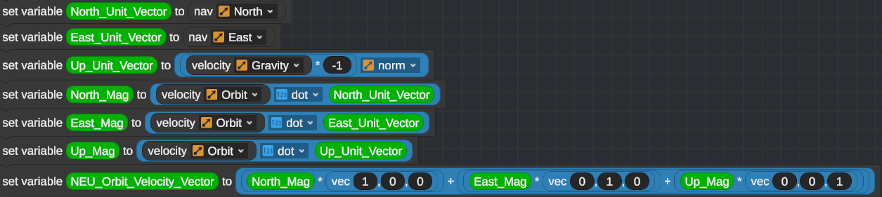
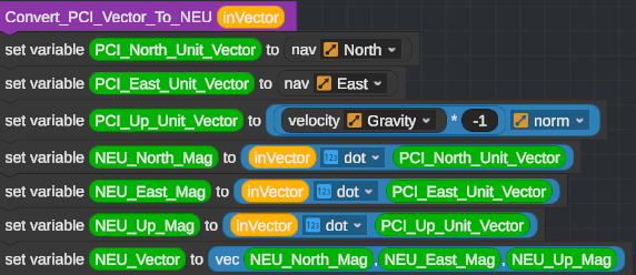
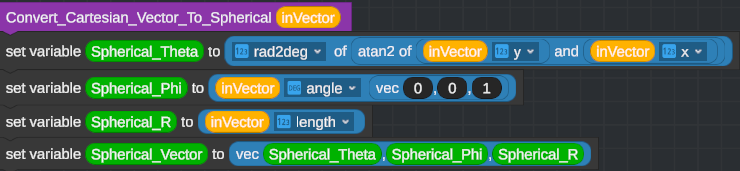
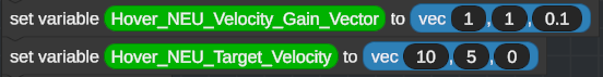
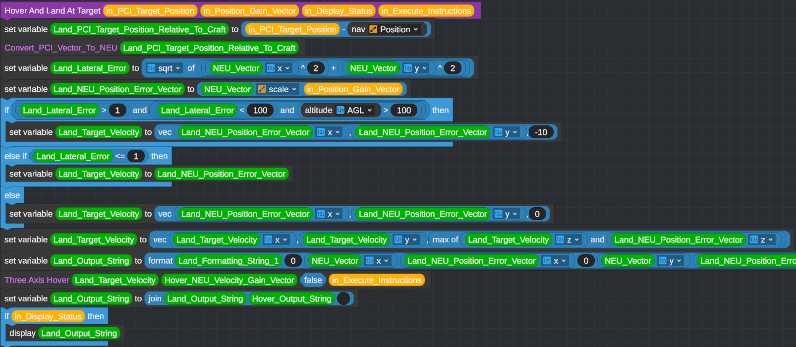
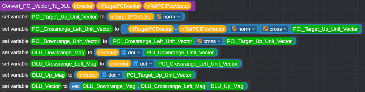
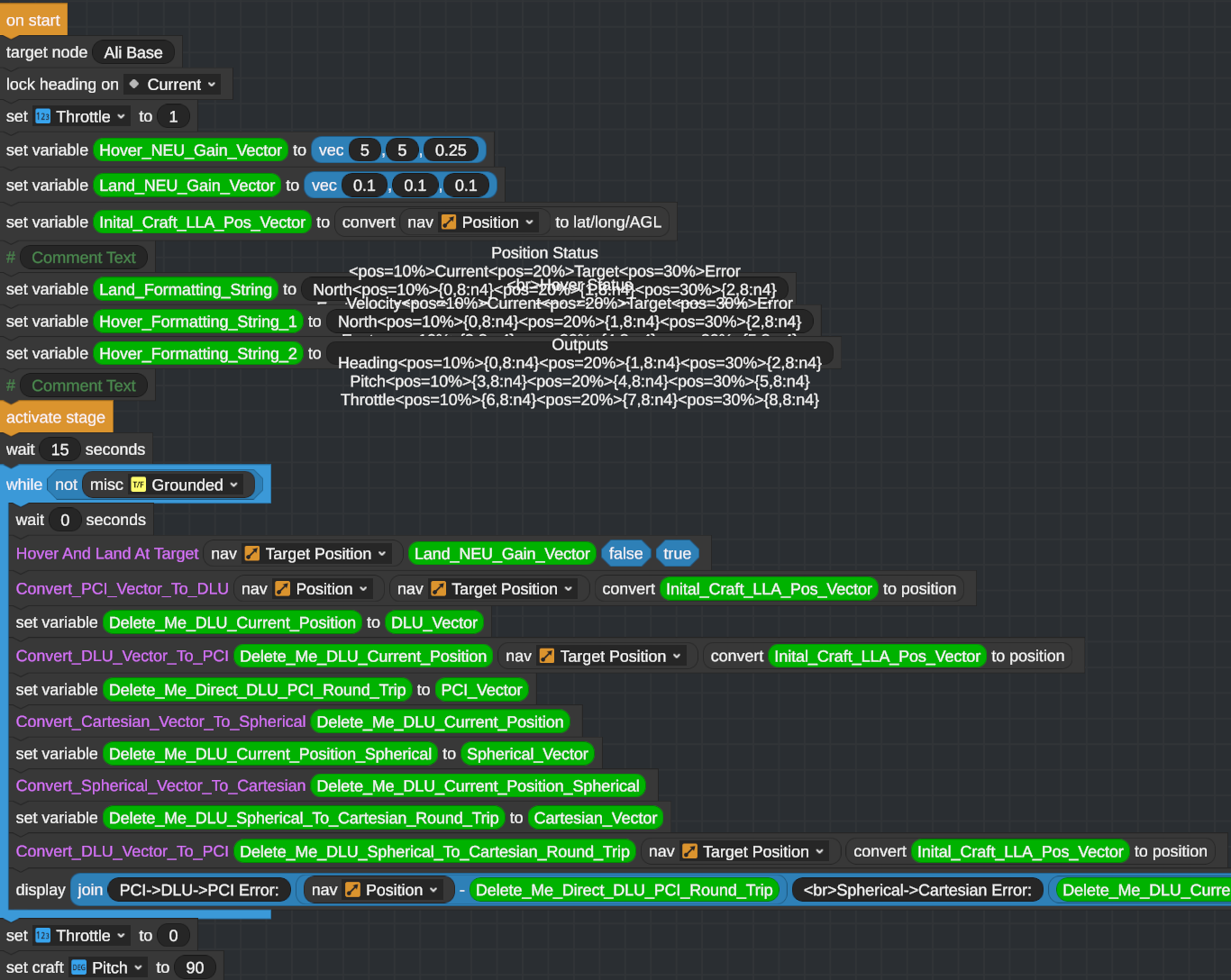
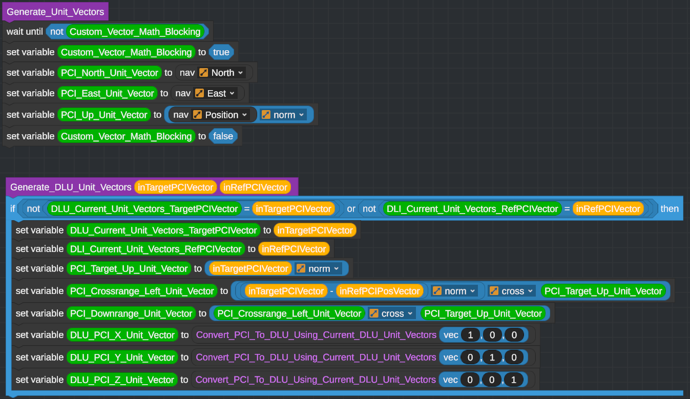
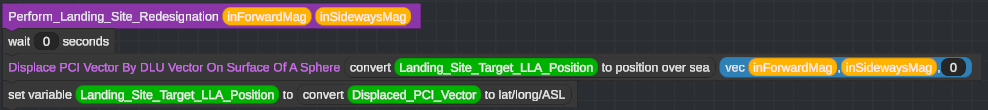
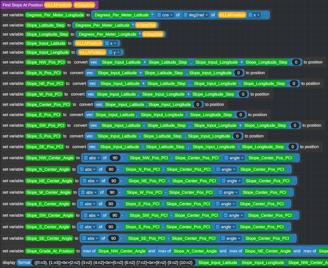
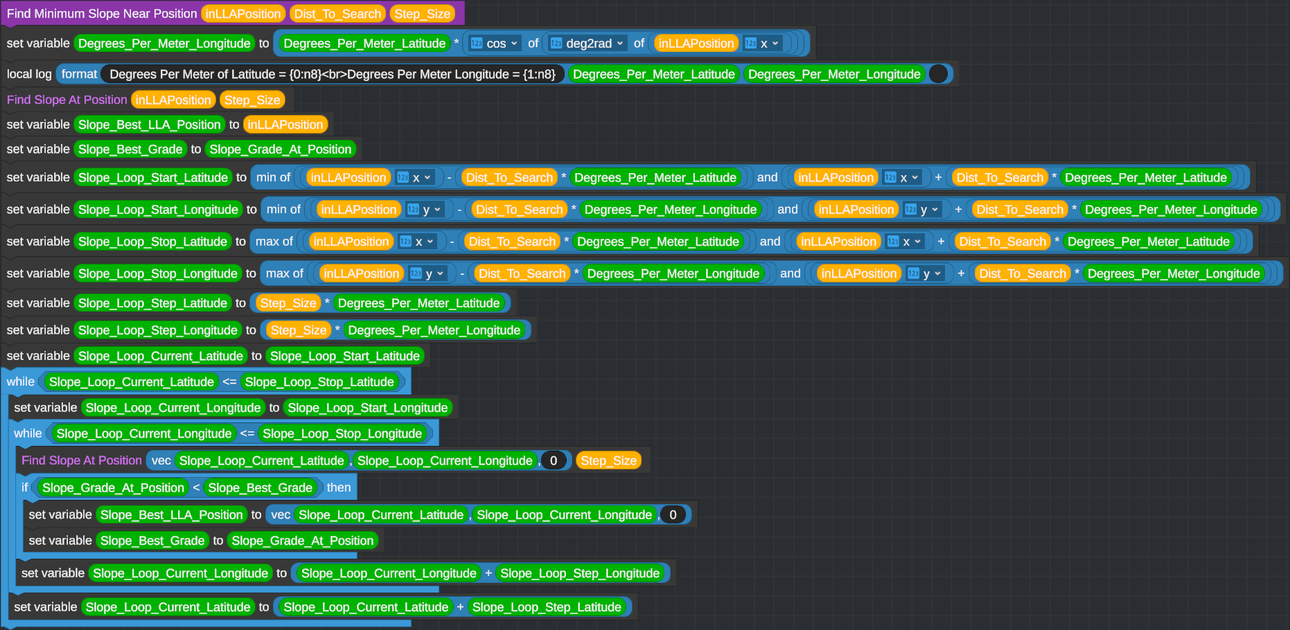
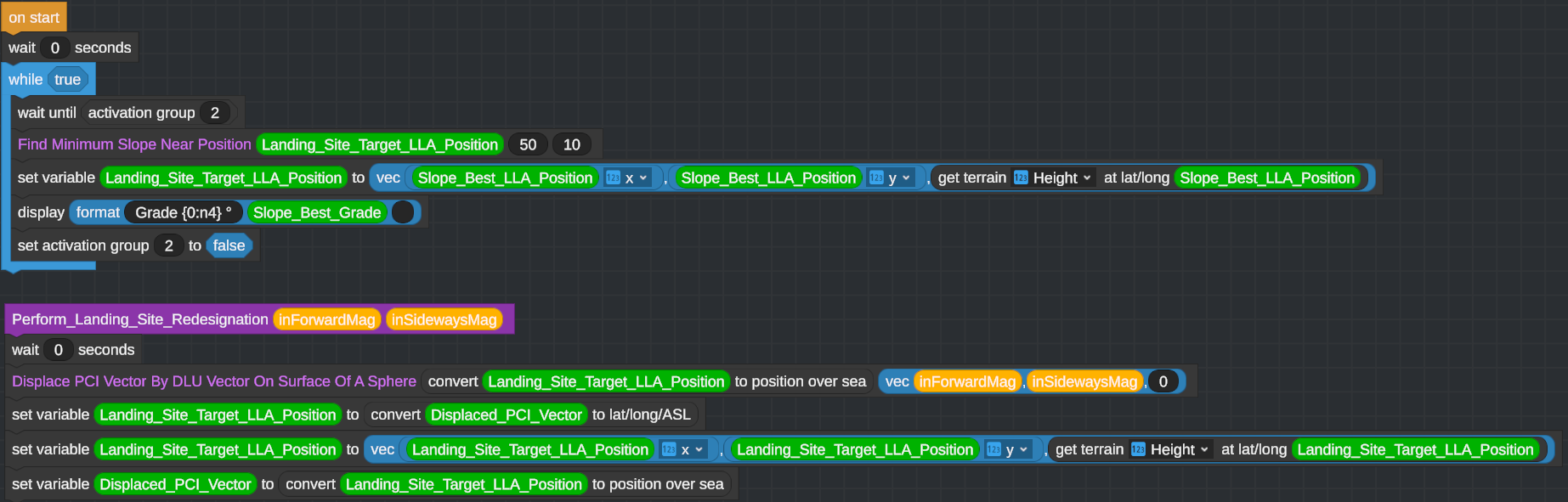
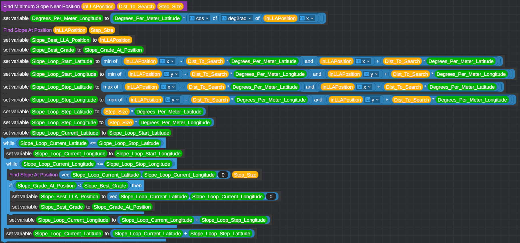
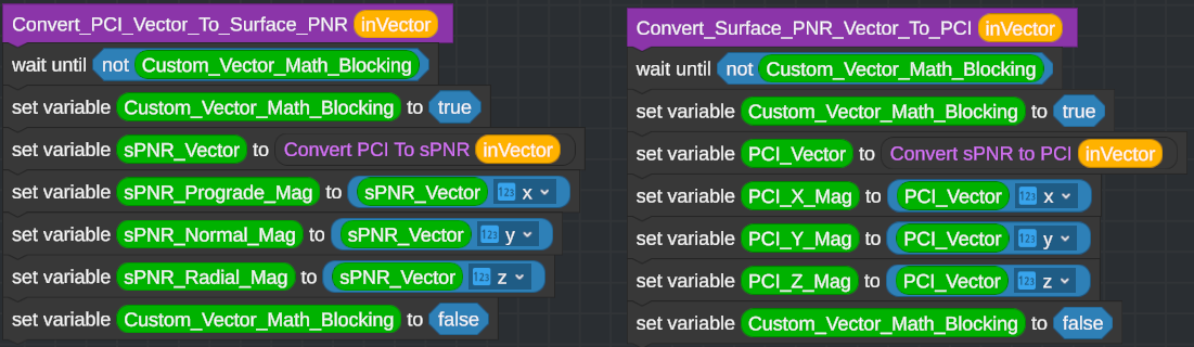
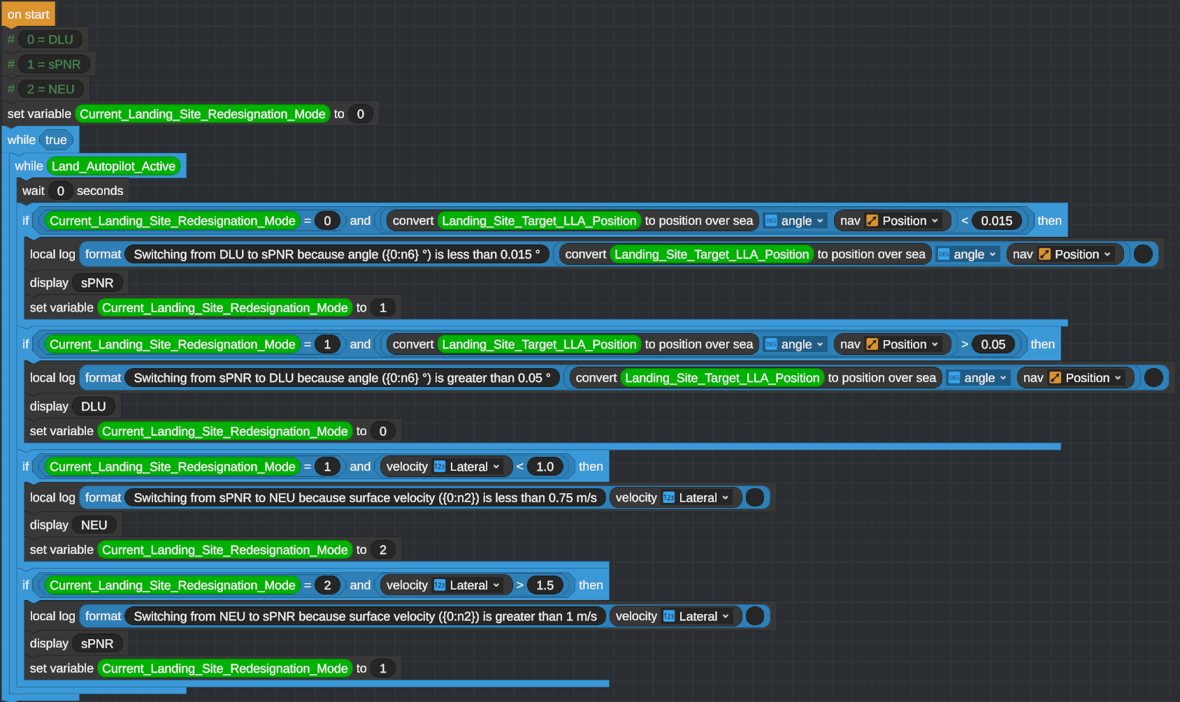
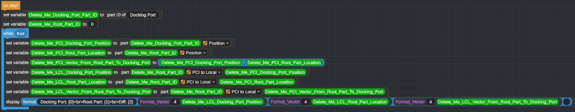
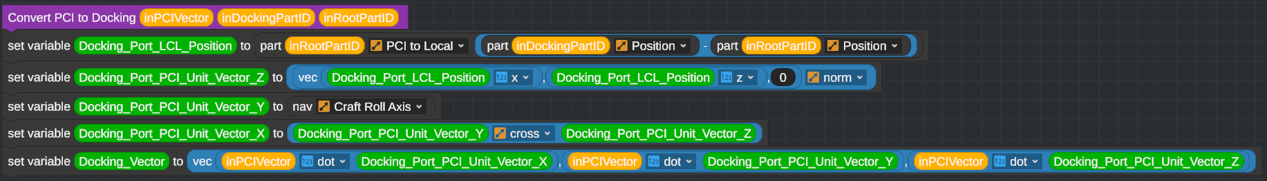
It is just 0, NEU_Vector(x), Land_NEU_Position_Error_Vector(x) repeated three times, swapping x for y and z. The leading 0 is also repeated in each iteration, so (very abbreviated) the full set of parameters is 0, V(x), E(x), 0, V(y), E(y), 0, V(z), E(z).

The reason for the repeated zeros is that the crafts current position defines the origin of the coordinate system being used, so it is always at (0, 0, 0).
lucasgslarson Dec 23, 2024 @ 6:10am 
in the hover and landing script, in the screenshot for the custom instruction "Hover and Land at target", the land output string is not fully in view. Does anyone know what full line is?
benchenbw Sep 21, 2024 @ 6:54am 
Magnificent guide, helped me a lot when I first play the game.
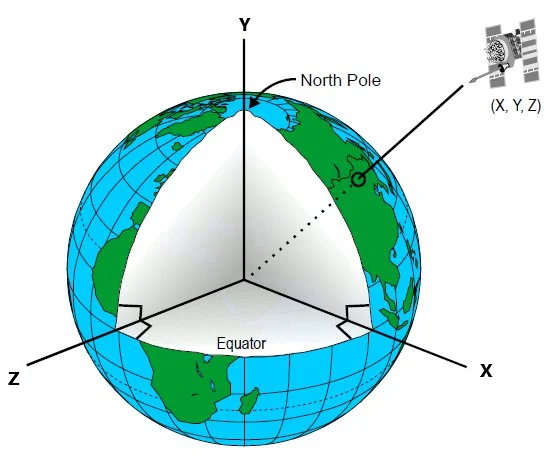
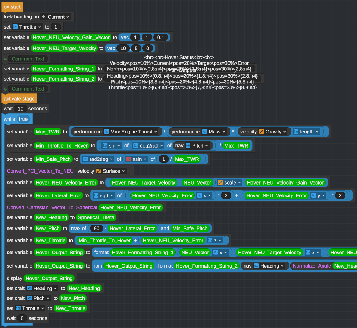
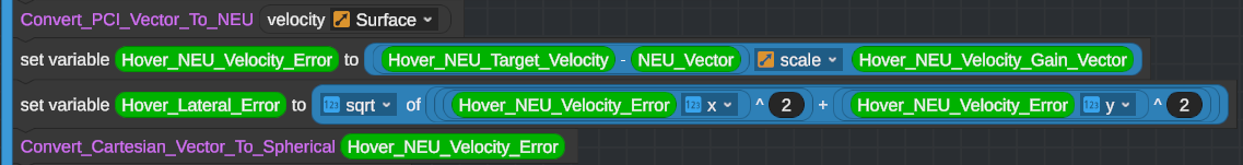
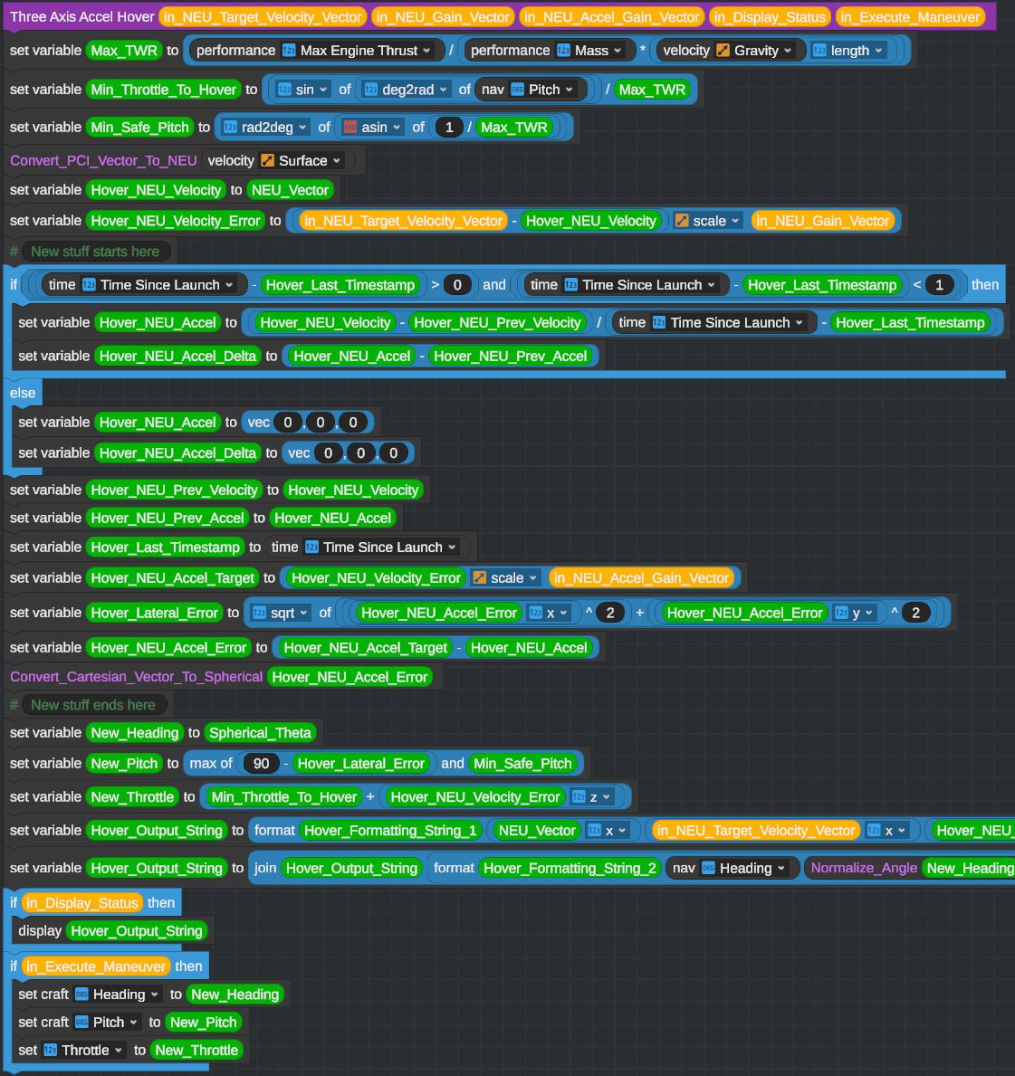
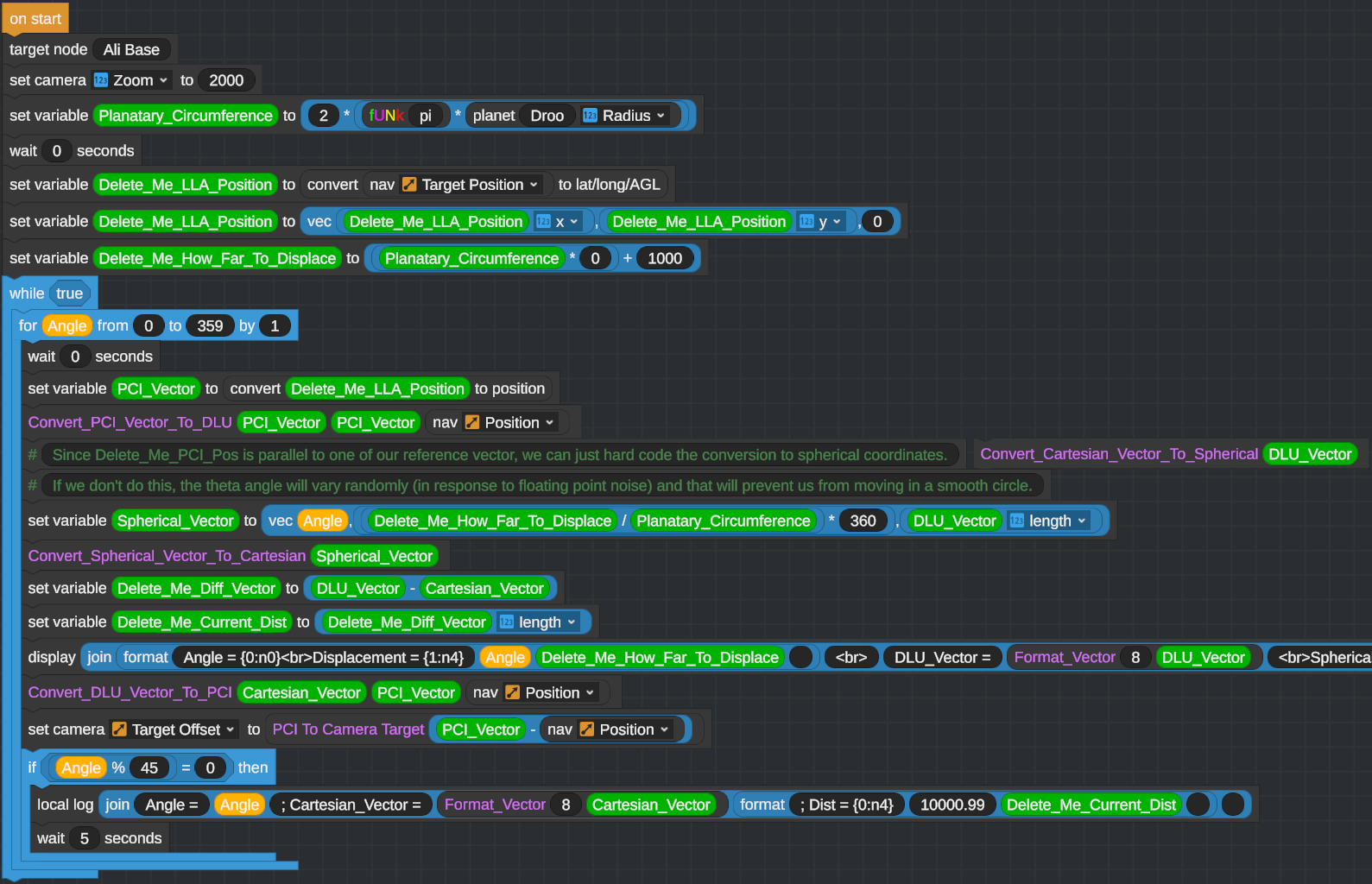
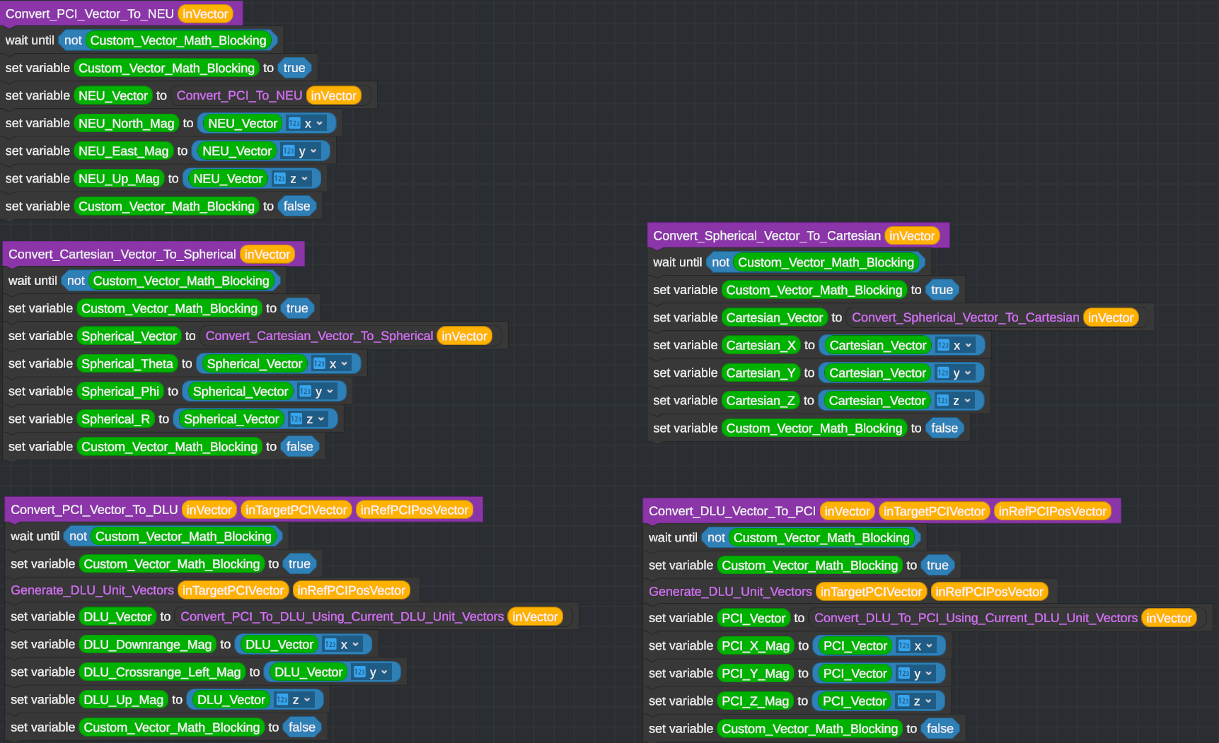
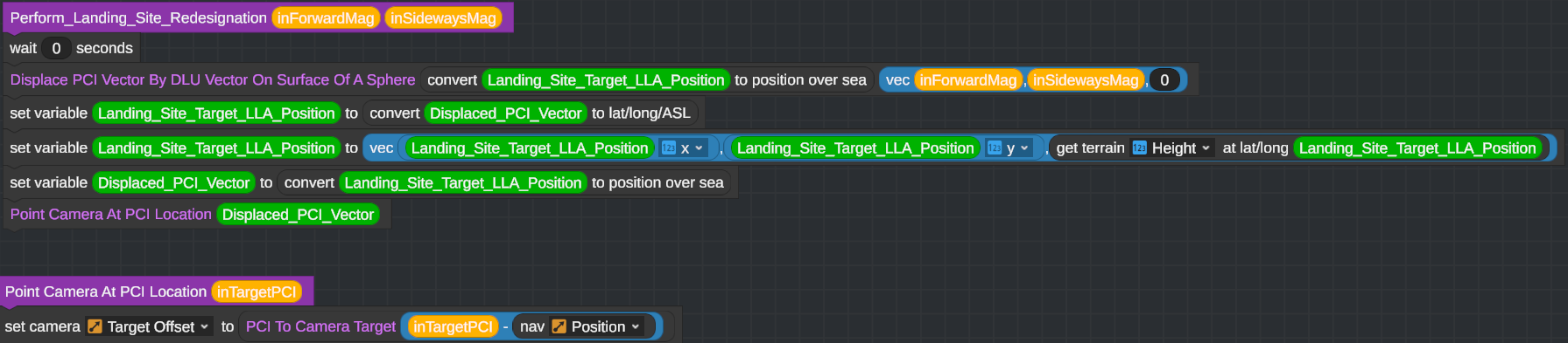
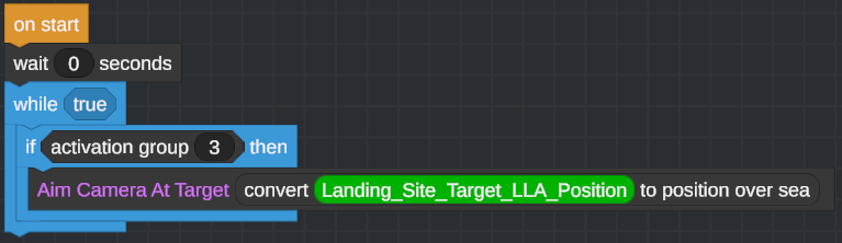
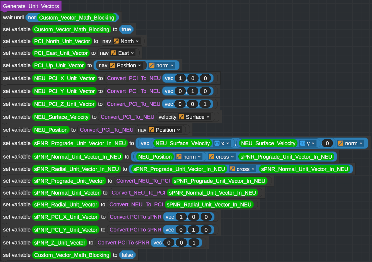
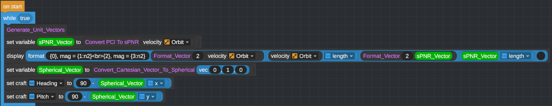
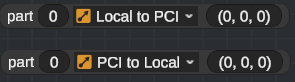
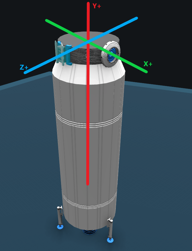
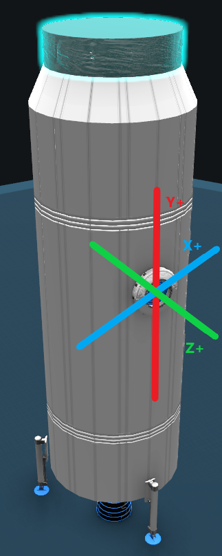
I believe the Z axis in the diagram shows the PCI coord system(the "Redefining axes for fun and profit" section) is in its opposite direction
AlwaysBeBatman Nov 27, 2023 @ 1:27pm 
Hi @mreed2!
Did you ever hear back from Steam about fixing their platform, or recovering your work?
This guide is a great resource. Let me know if I can help reconstruct it.
mreed2  [author] Oct 28, 2023 @ 10:41am 
Unhappily, this guide was authored directly in Steam. While I have a local copy of all the images, that's all I have -- the text only exists in the Steam guide.

Assuming I don't get back a helpful response from Steam, I'm considering rewriting the guide on GitHub or similar. While it would be a pain to do so, at least it would be much less likely that my guide would glitch out after a few months.
AlwaysBeBatman Oct 28, 2023 @ 10:34am 
@mreed2: I completely understand the need to resolve the root cause before investing significant effort in putting the images back on an unreliable platform. This situation must be incredibly frustrating for a content creator.

I also understand that you don't want to share the .xml source code files. Would you be willing to put the images in a zip file and share it? (email, file sharing site, etc.)
mreed2  [author] Oct 28, 2023 @ 6:47am 
"...IIRC, the last time was when I attended Va Tech in the early 1980s - In case the young folks are wondering, Yes, vectors were already a thing last centrury ;)..."

Me too! (well, not Va Tech, but you get the picture). That's why I wrote this guide -- I figured that there were a significant number of people that realized that "Vectors can do some spiffy stuff, but I don't quite remember the details" to fill in the gaps in knowledge.
mreed2  [author] Oct 28, 2023 @ 6:29am 
This... May not be reasonably fixable.

The issue is that the majority of the images in the guide have disappeared. And Steam won't allow me to re-upload the images either. I can rename the images and then they upload without issue, but since the image name has changed I then have to update the guide text to point at the new image. Given that there are 50 images that have disappeared this is close to "Rewrite the guide from scratch," and given that I don't know why it happened in the first place, it seems... Risky to spend hours (literally) re-uploading images only to discover that they disappear again after a few months.

For what its worth (not much, I suspect), I've opened a Steam support ticket to see what they say.