Microsoft Flight Simulator

Microsoft Flight Simulator

97 ratings
Cessna 152 - Cockpit Walkthrough and Basics
By AlexGB
A guide that explains the usable systems and basic operation of the Asobo Studio Cessna 152 for those new to flying as a whole or just to the Cessna 152.
3
4
8
2
2
   
Award
Favorite
Favorited
Unfavorite
──Introduction──
The Cessna 152 is one of the most popular training aircraft in flight schools worldwide, with over 32,000 being built. This is a great reason to learn to fly this plane in the simulator, especially if you want to fly in real life, as there is a good chance you'll end up in the cockpit of one of these. This guide is designed to help people new to flying or just new to the Cessna 152. Also the in-game tutorials use this plane so I recommend going off and trying them before reading this guide. That being said, I will still include the basics that you learn in that series of tutorials in this guide to refresh your memory.

DISCLAIMER: I am not a qualified pilot but I am working towards my PPL in this aircraft and have an understanding of how the aircraft works based on knowledge from real-world documentation.
Basics of Flight
Before we get into how to fly this specific plane, it is vital to understand the basics of fixed wing aviation, here is a diagram I modified to show the 3 axes along which the plane can be moved.

The axes of flight

Hopefully this makes sense, but as a brief summary: pitch moves the plane up and down, roll tilts the plane to the left or right, and yaw slides the plane to the left or right. Now lets move on to how you, as the pilot, can manipulate these axes to fly the plane.

Control Surfaces

The movable surfaces of the Cessna 152, shown in the colours: yellow, green, red, blue and orange

Yellow | Ailerons - Used to control the roll of the plane. Moving the yoke (see below) to the left will role the plane to the left and vice versa.
Green | Wing Flaps (Flaps) - Used to keep the plane in the air at slower speeds, usually at landing. There are instructions on how to use these in the Cockpit Walkthrough section of the guide.
Blue | Elevators - Used to control the pitch of the plane. Pulling the yoke (see below) towards you will raise the nose of the plane and pushing it away from you will lower the nose.
Red | Rudder - Used to change the yaw of the plane. Controlled using the rudder pedals (see below) Pushing your left foot forward will cause the plane to yaw to the left, and vice versa.
Orange | Trim - Used to keep the plane flying level without having to manually change the pitch of the plane. Covered in depth in the Cockpit Walkthrough section of the guide.

This is a yoke, it is used to control the elevators and ailerons of the plane

These are rudder pedals, they are used to control the rudder of the plane

This may sound like a lot to learn but if you do a free flight in the simulator you should be able to figure all this out by yourself pretty quickly.
──Cockpit Walkthrough──
The main point of this guide is to be an in-depth walkthrough of the cockpit of the Cessna 152, so this will be the biggest section.

DISCLAIMER: I’ll only be going through the systems that are operable in the Asobo Cessna 152, and therefore this guide will miss out some systems that are present in the real aircraft.
Main Panel
The main instrument panel of the Cessna 152

1 : Airspeed Indicator – Displays indicated airspeed in knots (KIAS) on the outside of the dial and miles per hour on the inside. The white arc that goes up to 85 knots represents the flap operating range, you don’t want to exceed the white arc without fully-retracting the flaps first. The green arc represents the normal operating speeds of the aircraft, and the yellow arc represents speeds you should only fly with in smooth air. The red line represents the maximum speed before structural faliures are likely to occur. The beginning of the green and white arcs represent the stall speed

2 : Artificial Horizon – A gyroscope that indicates the attitude (relative orientation) of the aircraft. With blue indicating the sky, brown indicating the ground, and where they meet the horizon. The orange arrow on top represents the aircraft’s angle of bank relative to the horizon. As the aircraft rolls the orange arrow will pass through marked lines on the top half of the display, from the middle out, indicating 0, 10, 20, 30, 60 and 90 degrees angle of bank. Note that the gyroscope only works when the engine is running.

3 : Analogue Clock

4 : Altimeter – Displays the aircrafts current altitude (height) in feet. The longer needle represents hundreds of feet and the shorter needle represents thousands of feet. The service ceiling of the cessna 152 is 14,700 feet so its advised that the aircraft stays below that altitude for good performance. The knob can be used to calibrate the altimeter to the outside atmospheric pressure either in Inches of mercury (Hg) or Millibars (mb) to make sure the instrument reads correctly.

5 : Course Deviation Indicator (NAV1) – Used for navigation, it can be tuned to receive frequencies from VOR beacons on the ground and direct the aircraft towards it. This can also be tuned to an ILS (Instrument Landing System) frequency which allows the pilot to follow the glideslope down to the runway when visability is bad. These systems are modelled fairly accurately in the Asobo Cessna 152, however I won’t be covering CDI procedures in this guide.

6 : Turn Coordinator – The aircraft on this display shows the rate of turn (rate of change in heading) by banking towards the direction of turn with varying intensity depending on how fast the rate of turn is. It is important to remember that this is not a bank indicator and not to use it as such. The tube with the black dot in the middle represent the balance of the aircraft, during normal flight operations, it is good practice to use the rudder to keep the ball in the center to keep the aircraft well balanced or ‘coordinated’. On the outside of the dial, the 2 markers below the horizontal lines represent a standard rate of turn. This means that if you hold the aircraft on either one of those lines and hold the ball in the center it will take two minutes to complete a 360° turn. This can be hard to understand on paper so I recommend you go into the sim and play around with this in the air.
A coordinated right-hand turn on the Turn Coordinator

7 : Suction Gauge – Indicates the pressure available to power instruments such as the attitude indicator and heading indicator that require vacuums to operate. As long as the needle points somewhere in the green arc, there is a sufficient vacuum to keep the instruments working.

8 : Heading Indicator – Indicates the direction the aircraft is pointing in relation to compass bearings. The instrument must be manually calibrated to the compass (see ‘upper cockpit’) from time to time to make sure it is pointing in the right direction.

9 : Vertical Speed Indicator – Indicates if the aircraft is going up or down and how fast. The needle will point to the upper half of the display if the aircraft is going up and the lower half if it is going down. Each notch on the outside of the dial represents 100 feet per minute. This instrument is most useful when holding altitudes where the needle should be pointing to the zero on the left of the dial.

10 : Course Deviation Indicator (NAV2) – Identicle in operation to the first CDI (NAV1). It can be used in tandem with NAV1 for more complicated procedures like locating a specific point in range of two VOR beacons, but I won’t be covering how to do that in this guide.
Centre Column
The centre column of the Cessna 152

1 : Carburetor Heat Control – This is used to control the amount of hot air going into the carburettor. It is used to prevent icing in the engine which can cause engine damage or failure. If the air outside is cold or humid, carb heat should be applied by pulling the plunger out. It should also be applied when the RPM isn’t in the green arc whilst flying, for example when on the base or final leg. Also note that applying carb heat reduces RPM slightly.

2 : Throttle – Main way to control power output from the engine, the power will increase as the throttle is pushed forward and vice verca.

3 : Mixture – Used to adjust the fuel/air mixture which controls the efficiency and power of the engine. When the plunger is fully out fuel is stopped from entering the engine and when pushed fully in the mixture is full rich. The Mixture should always be full rich when starting the engine and/or below 3000 feet barometric altitude (altitude relative to sea level). Above 3000 feet leaning the mixture by pulling the plunger out slightly will increase RPM. This is because as the air gets thinner as the aircraft goes higher, the air/fuel ratio changes and the mixture becomes too rich, leaning the mixture will fix this issue and restore the optimal air/fuel ratio.

4 : Wing Flaps – This control surface is used to increase lift at lower speeds, it also slows the aircraft down. There are 4 main stages of flaps on the Cessna 152: 0° (Up), 10°, 20° and 30° (Down). These are only used on take-off during a Short Field Take-off and even then flaps are only set to 10°. They are only really used on the base and final leg to slow the plane down and maintain adequete lift until touchdown.

5 : Trim Wheel – Trim is a way to reduce the pilot’s workload whilst the aircraft is in flight. When set properly, it maintains the aircraft’s pitch at a certain speed and altitude without the pilot having to manually control the elevators using the yoke. Nose up trim is set by scrolling the trim wheel downwards and vice verca. The current position of the trim is shown on the left of the trim wheel with a dot. You should always make sure the dot is aligned with the TAKE OFF marker before taking off, this means the aircraft is trimmed neutrally and the plane won’t randomly pitch up or won’t pitch up at all during take-off.
Right-Hand Panel
The right-hand panel of the Cessna 152

1 : Electronic Communications and Navigation Box - See under (Radio Panel)

2 : Tachometer – This instrument displays the RPM of the engine. Each notch represents 100 RPM. The green arc is where the needle should be in the climb and cruise, the red should not be surpassed under any circumstances. When the plane is in the air and the needle is below the green, Carb Heat should be applied.

3 : ADF Needle - This instrument is used in tandem with the ADF Box (see no.6) to find the direction towards a waypoint. It will point in the direction you need to point the plane in when tuned properly.

4 : Ammeter - Displays the amount of electricity being produced by the alternator compared to the amount being used up by the aircraft's electrical systems. When the plane is powered on, the ammeter should always read 0 (top middle of the gauge)

5 : Flight Hour Recorder - Displays the time the aircraft has been running in a flight session. Not really vital in the simulator but a nice addition.

6 : ADF Navigation Box - ADF Navigation (Automatic Direction Finder) is a method of navigation used in smaller planes to find the direction to a waypoint within a certain range, in some aircraft like the Cessna 172, it tells you the distance to the waypoint too. In the Cessna 152 however, it only shows the direction with the needle (3 : ADF Needle). To tune this to a frequency, turn the 3 knobs to display a 3 digit code. For example London City is 322.

A closer look at an ADF Navigation Box when powered on
Radio Panel
The radio panel (or Electronic Communications and Navigation Equipment) on the Cessna 152

1 : COMM1 – This is the main box where you tune into air traffic control. To use it make sure the knob in the bottom left is not pointing to the 'off' sign, then turn the knob on the bottom right of the box until the desired frequency is showing (In this case 124.850)above the STBY label. Next press the button with two arrows on it to swap the STBY frequency to USE, now you are ready to talk to air traffic control using the ATC tab.

2 : COMM2 – Identical to COMM1, can be used to tune into two frequencies at once if desired.

3 : NAV1 - Used to navigate with the Coarse Deviation Indicator 1 (see Main Panel). As I said before, I won't be covering how to do these just yet but may add them to the guide at a later date.

4 : NAV2 - Identical to NAV1 except it controls Course Deviation Indicator 2.

5 : Transponder - This is used to convey data like your altitude to air traffic control. When they need to, ATC will give you a 4-digit code to put into the transponder, in the sim, you can get the co-pilot to do this for you.
Upper Cockpit
The instruments above the windshield

1 : Magnetic Compass – Magnetic compass displaying the aircraft's heading while on the ground or in straight level flight. It doesn't work while the aircraft is banking so while in flight it is necessary to use the heading indicator. The heading indicator drifts over time so every so often while in stable straight flight it should be tuned to the compass to display an accurate reading.

2 : Thermometer - Thermometer displaying the temperature outside the aircraft in °C and °F.
Lower Cockpit
The area in between the seats on the cockpit floor

1 : Fuel Selector Valve – Controls the valve that determines whether fuel can enter the engine or not. When set to the OFF position (when the handle is pointing upwards), fuel is cut off from flowing from the fuel tanks to the engine. When set to ON, fuel is allowed to flow to the engine and combustion can occur. This is set to ON before engine start and under normal circumstances is not touched again until the aircraft is shut down after the flight.
15 Comments
AlexGB  [author] Nov 26, 2021 @ 2:14pm 
The key to holding pitch trim is to get the plane stable first, hold the attitude you want to maintain using the stick and then adjust your throttle to keep the same speed whilst holding the stick. Once the plane is holding the desired attitude and speed, then slowly trim and take pressure off your stick until it holds its self. This is quite hard to explain but I'm sure there are plenty of tutorials on Youtube if this explanation doesn't cut it. Hope it helped you out.
Lu Motta Nov 25, 2021 @ 7:17am 
Question: I'm not new to fs- played since it was on a tandy floppy.
my step son gifted me msfs 2020 last week, had fsx-se .
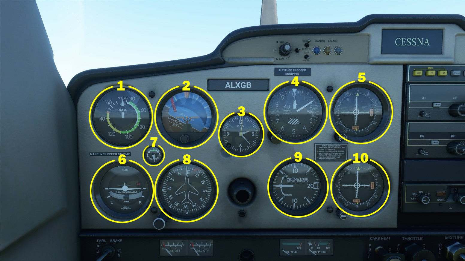
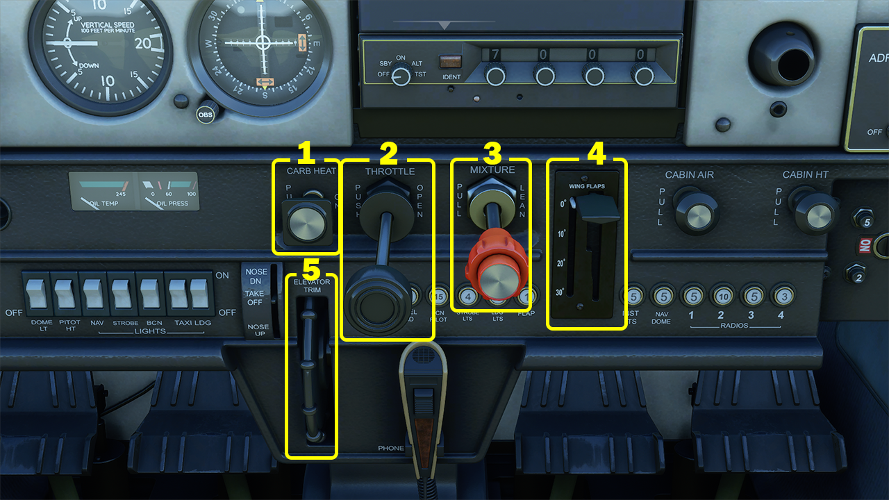
I'm getting the "hang of fs2020 BUT one thing is driving me batty right now-
HOLDING TRIM.......I CAN ADJUST UP OR DN BUT NOT HOLDING PROPER TRIM
AlexGB  [author] Jan 11, 2021 @ 10:29am 
No problem, I'll be adding the lower section of the main panel soon.
Lobos_De_Noche Jan 10, 2021 @ 3:43pm 
You are awesome! Thanks a million.
shelljen Dec 19, 2020 @ 11:28am 
Very good info. great job !
cwprice06 Dec 12, 2020 @ 8:22am 
excellent formation and visual
AlexGB  [author] Dec 4, 2020 @ 11:56am 
Glad it helped you out :)
Buanzo Dec 3, 2020 @ 1:33pm 
This is a great guide, now I understand mixture :)
Jorge Nov 8, 2020 @ 12:05pm 
Nice, it´s a great work. thanks Alex
Vincat Oct 16, 2020 @ 2:12pm 
nice.. thanks!!